Method and apparatus for a vehicle forward direction signal

a forward direction and signal technology, applied in mechanical visible signalling, instruments, transportation and packaging, etc., can solve the problems of insufficient signal for proceeding in a straight forward direction, failure to address a directional signal, and confusion of other drivers, so as to reduce medical and automotive insurance rates, prevent automotive accidents, and increase the visibility of the indicator system

Inactive Publication Date: 2010-10-05
WILLIAMS GEORGE LAMONT
View PDF19 Cites 5 Cited by
  • Summary
  • Abstract
  • Description
  • Claims
  • Application Information

AI Technical Summary

Benefits of technology

[0014]An advantage of the present invention is to prevent automotive accidents and reduce medical and automotive insurance rates by adding an indicator signaling a driver's intention of proceeding in a straight ahead manner. The indicators in the system may be placed in a variety of different locations on the vehicle allowing for high visibility. Preferably, the indicator lights may be viewed from a variety of positions relative to the vehicle, such as from the side of the vehicle or from the front of the vehicle. Further, the visibility of the indicator system is increased by incorporating lens(es) tinted in color or by using a clear lens and green LEDs.
[0015]The signaling device of the present invention is capable of being activated by different means such as voice, GPS, hand or foot. These activation means allows human operators to overcome any physical disabilities and still maintain a sense of safety for themselves and surrounding drivers.
[0016]The present invention includes at least one vibrating element, such that the element vibrates a steering column, armrest, portion of a seat harness, or other portion of a vehicle in order to provide a distinct feedback to a driver when the straight ahead signal switch is engaged. In one embodiment, the buzzer will vibrate in intervals with a 3 second vibration followed by a 5 second delay.
[0017]Further, the present invention allows for solar powered cells to be incorporated either in the housing or onto the lens. These cells allow for the present invention to be operated in an environmental-friendly and cost efficient manner.
[0018]Other objects and advantages of the present invention will become apparent from the following descriptions, taken in connection with the accompanying drawings, wherein by way of illustration and example, an embodiment of the present invention is disclosed.
[0019]Further advantages of the invention will be more clearly understood from the following description of illustrative embodiments thereof, to be read by way of example and not of limitation in conjunction with the apparatus shown. The beneficial effects described above apply generally to the ball cover disclosed herein. The specific structures through which these benefits are delivered will be described in detail hereinbelow.

Problems solved by technology

There is, however, a driving condition that can cause confusion to other drivers and that does not currently have an indicator to give notice of the condition.
Although the drivers need to signal their intentions to one another, there is no adequate signal for proceeding in a straight forward direction.
However, the '755 patent only provides for a U-turn indicator and fails to address a directional signal used when a driver is proceeding in a straight ahead direction.
Although the '990 patent indicates when a driver intends to brake or make a left turn or right turn, it expressly fails to provide for a signaling device designed to indicate when a driver is proceeding in a straight forward direction.
However, the '583 patent fails to claim and teach a vehicle signal device alerting surrounding vehicles of the driver's intention of proceeding in a straight forward direction.

Method used


Image

  • Method and apparatus for a vehicle forward direction signal
  • Method and apparatus for a vehicle forward direction signal
  • Method and apparatus for a vehicle forward direction signal

Examples


example

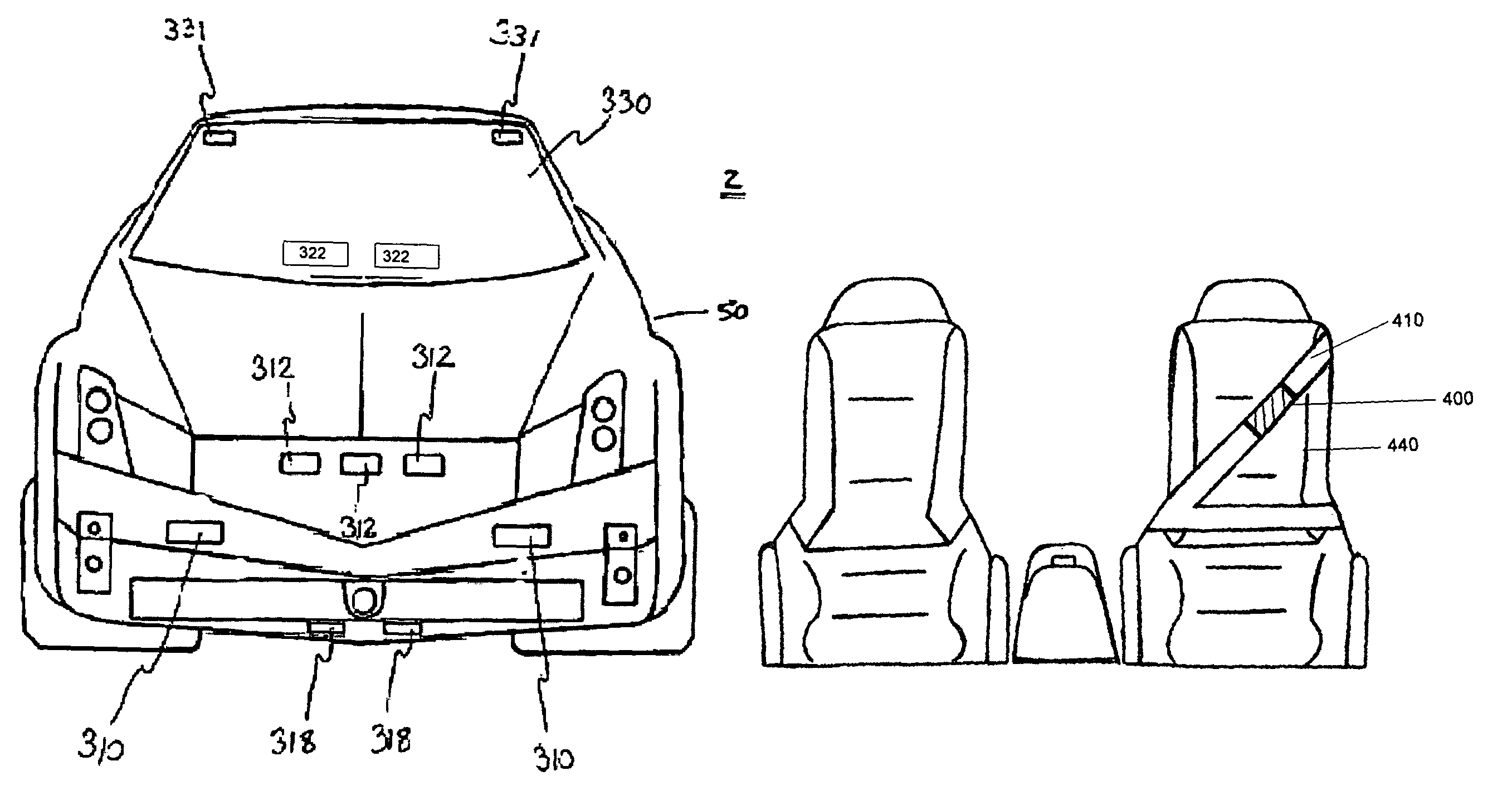
[0048]FIG. 9 is a front view of a seat harness with a buzzing pad 400. In this example, a buzzing vibration element is mounted on a portion of a seat belt or seat harness 410. One method of mounting the device is to place the device in a pocket of form fitting material and to removably attach the material to the seat harness with a hoop and loop fastening material. FIG. 10 is a front view of an indicator switch 430 mounted on the front edge of a driver's seat 440. The switch may be a wired to the indicator lights and the buzzing pad, or may communicate wirelessly with the lights and indicator. A wired connection may be established by running wires through a console adjacent to the seat and then through a lower portion of the front of the seat. This type of connection may be provided on an after-market indicator device for existing vehicles or on a new vehicle. In this example, two indicator lights are provided, with one light mounted on each of the side view mirrors of the vehicle.

[...


PUM


Abstract

A vehicle direction indicator system is designed to alert surrounding drivers of the intentions of the vehicle operator to continue in a forward direction. The indicator system has a plurality of indicator light end points and each end point is powered by the vehicle's electrical system and includes a housing, a light source holder and a lens attached to the front portion of the housing, and a vibration feedback element to indicate to the driver when the signal is activated. The end points may be positioned in various locations such as the grill, spoiler, side markers and the like and may simultaneously emit a color when the vehicle driver actuates the indicator system within the vehicle. The system is preferably mounted onto the front portion of the vehicle and is capable of signaling to other drivers at a four way intersection an intention to continue in a straight direction.

Description

RELATED APPLICATIONS[0001]This is a continuation-in-part application to application Ser. No. 10 / 963,121 which was filed Oct. 12, 2004 now abandoned, which was is a continuation-in-part application to application Ser. No. 10 / 620,848 which was filed Jul. 16, 2003 now abandoned, as a continuation-in-part application to Ser. No. 10 / 176,996 filed on Jun. 21, 2002 now abandoned, relating back to a provisional patent application having the Ser. No. 60 / 299,872 filed on Jun. 21, 2001 and incorporated in its entirety.TECHNICAL FIELD[0002]The present invention relates generally to a system and method for a forward signaling device, namely to a vehicle direction signaling device to indicate a vehicle proceeding in a straightforward direction.BACKGROUND OF THE INVENTION[0003]Signaling devices designed for motor vehicles are well known in the art. Since the earliest days of the automobile and other motorized vehicles, various indicator lights were added to the outside surface of the vehicle, acti...

Claims


Application Information

Patent Timeline
Patent Type & Authority Patents(United States)
IPC IPC(8): B60Q1/38B60Q9/00
CPCB60Q1/0035B60Q1/2661B60Q1/2665B60Q1/268B60Q1/32B60Q1/323B60Q1/50B60Q9/00B60Q2900/30B60Q2900/40B60Q1/325
Inventor WILLIAMS, GEORGE LAMONT
Owner WILLIAMS GEORGE LAMONT
Why Eureka
Try Eureka