Unlock instant, AI-driven research and patent intelligence for your innovation.

Frequency divider circuits

a frequency divider and circuit technology, applied in the field of frequency divider circuits, can solve problems such as unsuitable for many applications

Inactive Publication Date: 2010-10-05
FUTURE WAVES UK
View PDF11 Cites 2 Cited by
  • Summary
  • Abstract
  • Description
  • Claims
  • Application Information

AI Technical Summary

Benefits of technology

The solution enables the generation of clock signals with a 50% duty cycle for odd number divisions, enhancing the suitability of the frequency divider circuits for various digital processing applications by maintaining efficient operation across different division factors.

Problems solved by technology

This is not suitable for many applications.

Method used


Image

  • Frequency divider circuits
  • Frequency divider circuits
  • Frequency divider circuits

Examples


Embodiment Construction

[0025]FIG. 5 illustrates the state table for the divide-by-5 circuit of FIG. 2, but this time showing the states within each of the flip flops, i.e. the states for the individual D-type latches. The left hand column “N” shows the count, split into half clock pulses. In order to obtain an output with a 50% duty cycle, the output must be switched between counts (i.e. clock pulses) 4 and 0, and midway through count 2. We need to identify edges within the state table that can be used to generate appropriate switching signals. For the purpose of this example, we make use of the transition of the input to the first latch D0 from 0 to 1, and the transition of the input to the second latch D0i from 1 to 0.

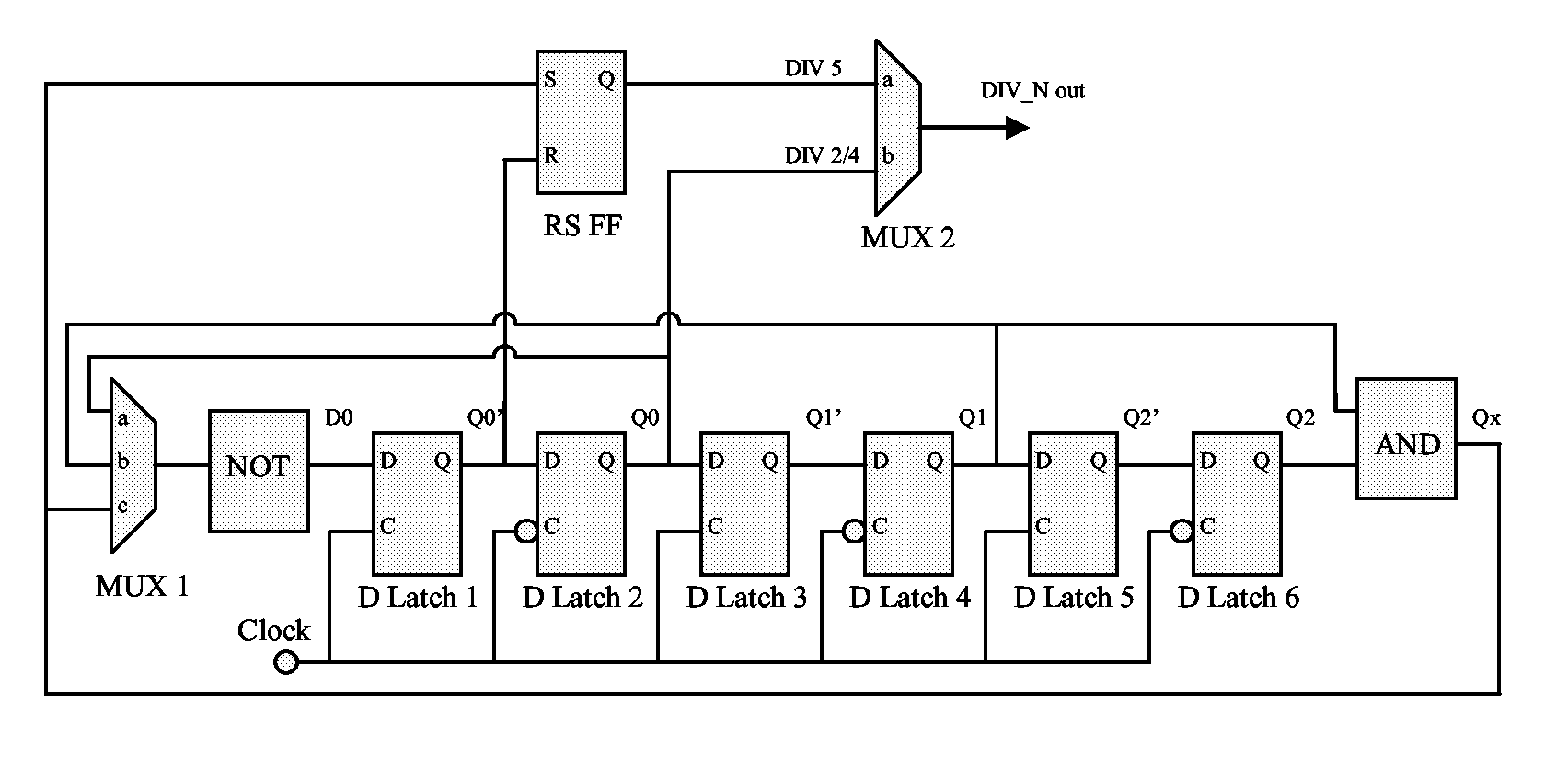
[0026]There is illustrated in FIG. 6 a divider circuit which is programmable to provide an output clock signal (DIV_N out) having a clock frequency which is 1 / Nth of the frequency of an input clock signal (Clock). According to this architecture, N may be 2, 4, or 5.

[0027]The circuit of FIG...


PUM


Abstract

A circuit for deriving an output clock signal from an input clock signal, the output clock signal having a frequency which is 1 / Nth of the frequency of the input clock signal, where N is an odd number. The circuit comprises a plurality of latches configured as a latch ring, the latches being arranged in successive pairs, each pair of latches comprising a first latch that switches on one of the rising or falling edge of the input clock signal, and a second latch that switches on the other of the rising or falling edge of the input clock signal. An RS flip flop is coupled to receive at one of its set and reset inputs an output from the latch ring that is switched on a rising edge, and at the other of the set and reset inputs an output from the latch ring that is switched on a falling edge. Said output clock signal is provided at an output of the RS flip flop.

Description

CROSS-REFERENCE TO RELATED APPLICATIONS[0001]This national stage application claims the benefit under 35 U.S.C. §371 of International Application No. PCT / GB2007 / 050016 filed on Jan. 15, 2007, entitled FREQUENCY DIVIDER CIRCUITS, which takes its priority from U.S. Provisional Application No. 60 / 761,363 filed on Jan. 24, 2006 and also takes its priority from GB Application No. 0604263.4 filed on Mar. 3, 2006, and all of whose entire disclosures are incorporated by reference herein.FIELD OF THE INVENTION[0002]The present invention relates to a frequency divider circuits, and in particular, though not necessarily, to frequency divider circuits based upon a Johnson ring architecture.BACKGROUND TO THE INVENTION[0003]Digital processing circuits require one or more clock signals to function. Clock signals are typically derived from a fundamental clock signal provided by a crystal oscillator. For example, a clock signal having a frequency lower than that of the fundamental clock signal can b...

Claims


Application Information

Patent Timeline
Patent Type & Authority Patents(United States)
IPC IPC(8): H03K25/00
CPCG06F1/3287G06F1/3203H03F3/45188H03F3/189H03K23/544Y02B60/1217Y02B60/1282H03F2200/492H03F2200/294H03F2200/372Y02B60/1278H03F2200/489Y02D10/00H03K21/00
Inventor MILLER, ROBIN JAMES
Owner FUTURE WAVES UK