Method and system to avoid inter-system interference for phase-based time-of-flight systems

a technology of phase-based time-of-flight and detection system, applied in the field of methods and systems, can solve the problems of determining erroneous data, affecting active light emitted by one system could interfere with the detection of reflected light emitters, so as to reduce the likelihood of inter-system interference between adjacent phase-based tof systems

Active Publication Date: 2008-07-29
MICROSOFT TECH LICENSING LLC
View PDF3 Cites 172 Cited by
  • Summary
  • Abstract
  • Description
  • Claims
  • Application Information

AI Technical Summary

Benefits of technology

[0028]Likelihood of inter-system interference between adjacent phase-based TOF systems is lessened by reducing the cross-correlation product P12 using at least one of two complementary aspects. Using either or both aspec

Problems solved by technology

The resultant inter-system interference or interaction can result in erroneous or corrupt DATA from each system.
But if vehicle 100-B has a similar system 100-B, interference between the two systems can result in each system determining erroneous data, e.g., corrupt DATA.
It will be appreciated that if more than one virtual input system were used in close physical proximity to another such system, active light emitted by one system could interfere with detection of reflected light emitter by the other system, and vice versa.
In a virtual keyboard application, the result would be misinterpreted keystrokes, e.g., many typographical errors.
As the popularity of phase-based TOF systems increases, the likelihood of inter-system interference from adjacent systems will increase.
In a virtual keyboard application,

Method used


Image

  • Method and system to avoid inter-system interference for phase-based time-of-flight systems
  • Method and system to avoid inter-system interference for phase-based time-of-flight systems
  • Method and system to avoid inter-system interference for phase-based time-of-flight systems

Examples


Embodiment Construction

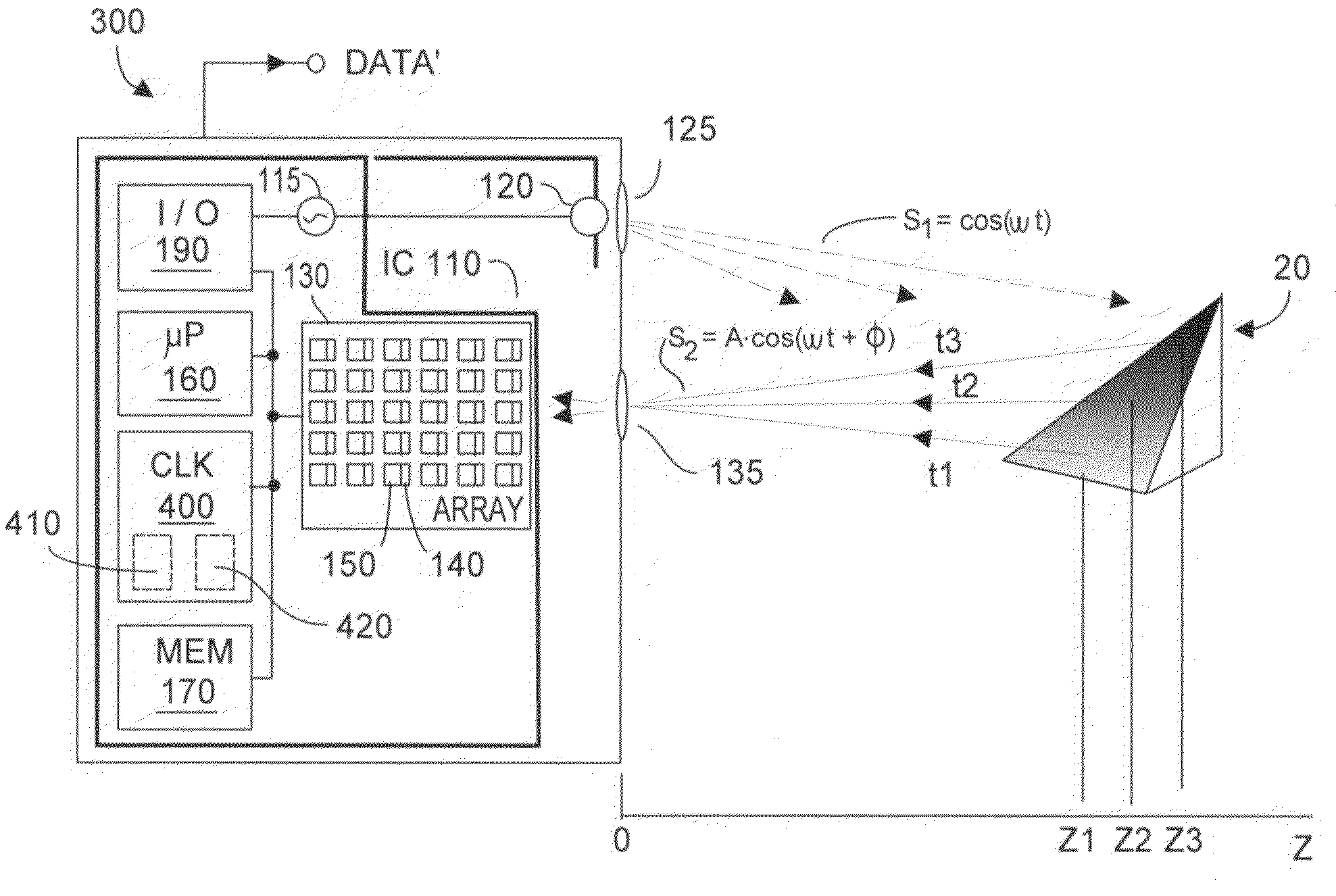
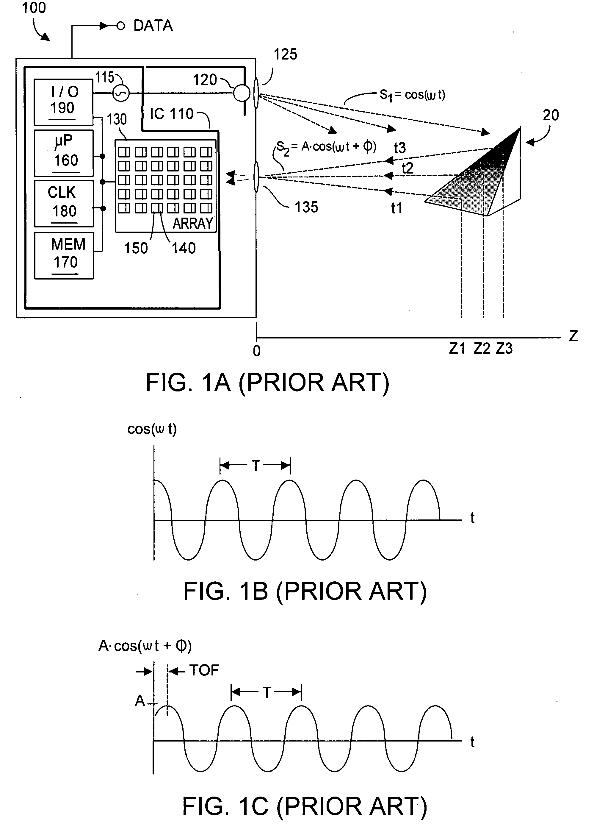
[0042]As noted, typically in prior art phase-based TOF systems, a high quality clock generator 180 (FIG. 1A) is employed. Understandably, implementing highly stable, low noise oscillators or clocks can be expensive. As will now be described, the present invention takes an approach quite opposite to the prior art in that noise in the high frequency clock signal is affirmatively nurtured. Referring now to FIG. 3, a phase-based TOF system 300 is shown in which prior art clock generator 180 is replaced with a clock generator system 400, according to the present invention.

[0043]Clock generator system 400 implements at least one and preferably two mutually complementary aspects to reduce the cross-correlation product P12. Advantageously, the present invention can randomize potential interference within a pixel detection integration period T, although randomization could also be employed across period T as well. Such randomization of interference within or across a detection interval can o...


PUM


Abstract

Inter-system interference cross-produce P12 is reduced in a phase-based TOF system by randomizing instantaneous phase and/or frequency within a capture interval (or detection integration period). In one aspect, the TOF clock system frequency preserves long-term clock frequency stability but intentionally includes random or pseudo-random clock noise. The noise ensures the generated clock signals are temporally imperfect and lack substantial perfect periodicity. A second aspect causes the TOF clock system to hop frequency, preferably pseudo-randomly. TOF system homodyning favors detection of optical energy whose frequency correlates to the time-varying frequency of the emitted optical energy. Thus, the varying spectral spacing of the emitted optical energy reduces likelihood that an adjacent TOF system at any given time will emit optical energy of an interfering frequency. At least one aspect is employed, both aspects being mutually complementary to reduce the cross-correlation product P12 without substantially affecting TOF system performance.

Description

RELATIONSHIP TO CO-PENDING APPLICATION[0001]Priority is claimed from U.S. provisional patent application Ser. No. 60 / 801,201, filed on 18 May 2006, entitled Method and System to Avoid Inter-System Interference for Phase-Based Time-of-Flight Systems, assigned to Canesta, Inc. of Sunnyvale, Calif., assignee herein.FIELD OF THE INVENTION[0002]The invention relates generally to phase-based time-of-flight detection systems that examine detected signal phase-shift to determine Z distances, and more particularly to avoiding inter-system interference when several such systems are operating in relatively close proximity.BACKGROUND OF THE INVENTION[0003]Time-of-flight (TOF) systems that provide a measure of distance (Z) from the system to a target object without depending upon luminosity or brightness information obtained from the target object are known in the art. See for example U.S. Pat. No. 6,323,942 entitled CMOS-Compatible Three-Dimensional Image Sensor IC (2001), assigned to Canesta, ...

Claims


Application Information

Patent Timeline
IPC IPC(8): G01C3/08
CPCG01S13/325G01S13/931G01S2013/9385G01S2013/9378G01S7/4911G01S17/36G01S17/894G01S17/931G01S2013/93272G01S2013/93274G01S7/0235
Inventor BAMJI, CYRUS
Owner MICROSOFT TECH LICENSING LLC
Why Eureka
Try Eureka