Chirp-managed, electroabsorption-modulated laser

a laser and a chirp-managed technology, applied in the direction of electromagnetic transmission, electrical equipment, transmission, etc., to achieve the effect of increasing the tolerance of fiber dispersion and extending the optical transmission length

Active Publication Date: 2010-10-05
II VI DELAWARE INC
View PDF83 Cites 22 Cited by
  • Summary
  • Abstract
  • Description
  • Claims
  • Application Information

AI Technical Summary

Benefits of technology

[0015]This invention provides an optical spectrum reshaper (OSR) which works in tandem with a modulated optical source which, by modifying the spectral properties of the modulated signal, results in extending the optical transmission length well beyond the dispersion limit. The OSR can be defined as a passive optical element that imparts an optical frequency dependent loss and frequency dependent phase on an input optical signal. This invention also provides a modulated laser source and an optical spectrum reshaper system that increases tolerance to fiber dispersion as well as converting a partially frequency modulated signal into a substantially amplitude modulated signal.
[0016]The optical spectrum reshaper (OSR) may be a variety of filters such as a Coupled Multicavity (CMC) filter to enhance the fidelity of converting a partially frequency modulated signal into a substantially amplitude modulated signal. The OSR may also partially compensate for the dispersion of the fiber. In one embodiment of the present invention, a modulated laser source may be provided that is communicatably coupled to an optical filter where the filter is adapted to lock the wavelength of a laser source as well as converting the partially frequency modulated laser signal into a substantially amplitude modulated signal.
[0052]tailoring the frequency characteristics of said second signal so as to extend the distance said second signal can travel along a fiber before the amplitude characteristics of said second signal degrade beyond a given amount.

Problems solved by technology

On the other hand, directly modulated lasers (DML) reach <5 km because their inherent time dependent chirp causes severe distortion of the signal after this distance.

Method used


Image

  • Chirp-managed, electroabsorption-modulated laser
  • Chirp-managed, electroabsorption-modulated laser
  • Chirp-managed, electroabsorption-modulated laser

Examples


Embodiment Construction

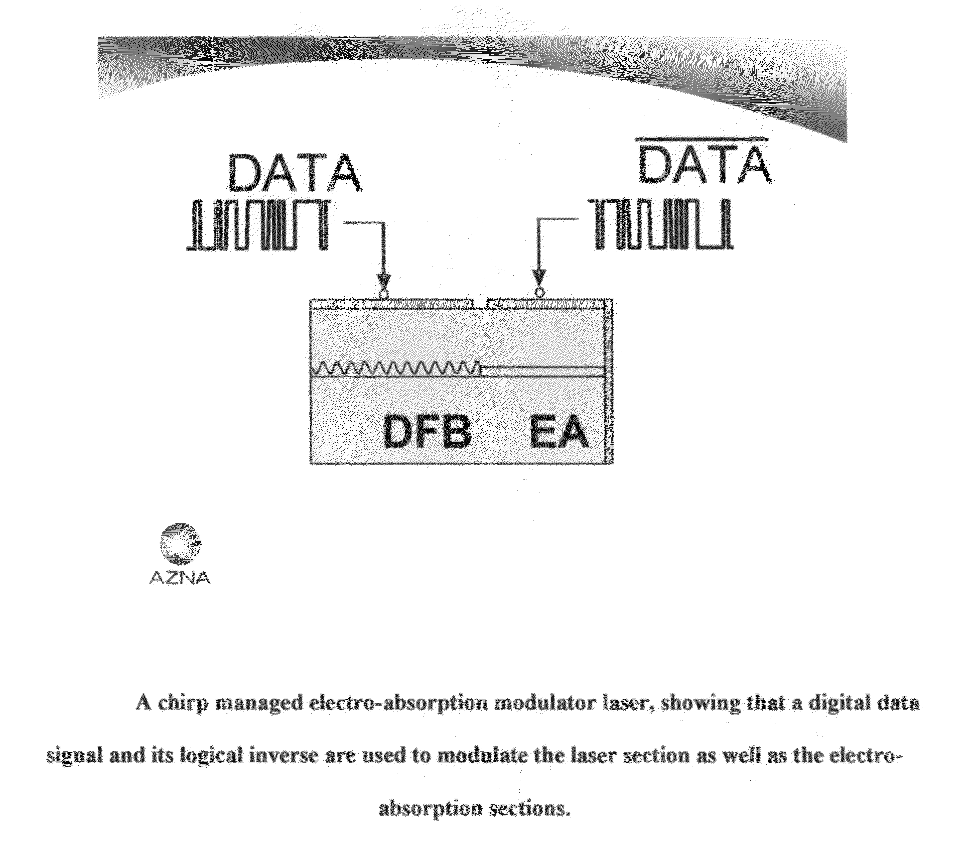
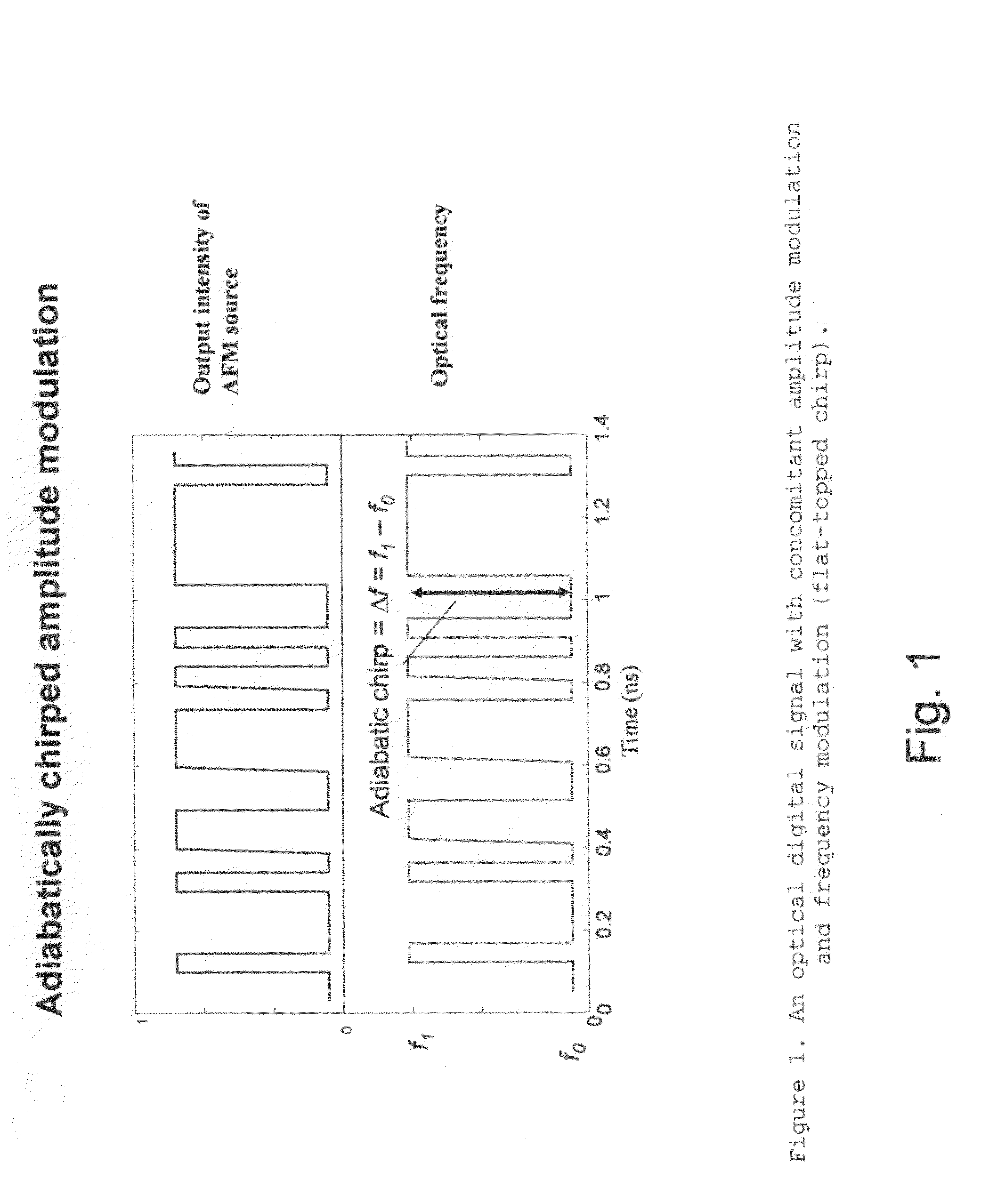
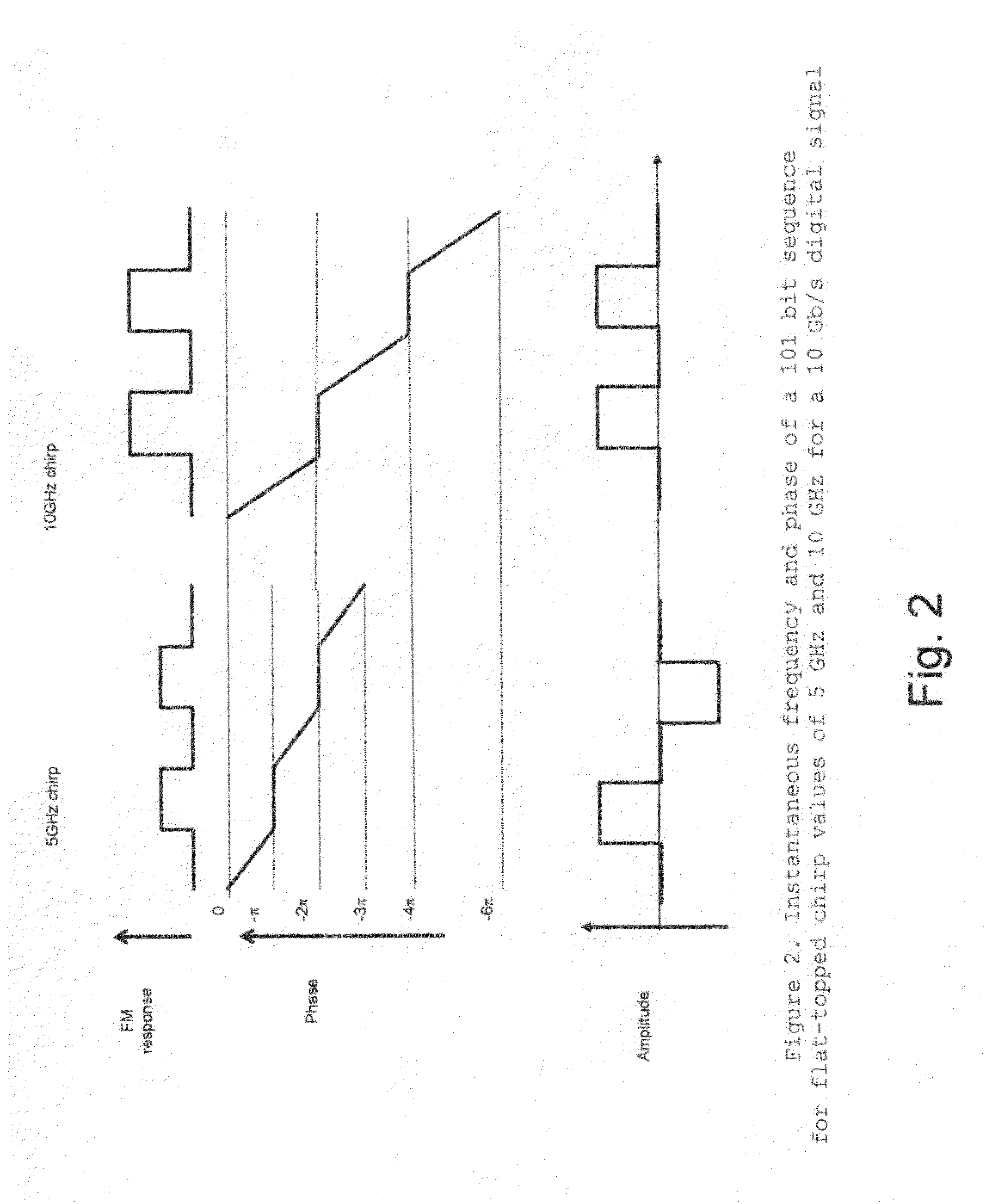
[0112]In one embodiment of the present invention, the CML™ generates a digital optical signal having concomitant amplitude and frequency modulation, such that there is a special correlation between the optical phases of the bits. This phase correlation provides a high tolerance of the resulting optical signal to dispersion in the optical fiber; further extending the reach of the CML™.

[0113]In one preferred embodiment of the present invention, the CML™ consists of a directly modulated DFB laser and an optical spectrum reshaper (OSR). The distributed feedback (DFB) laser is modulated with an electrical digital signal, wherein a digital signal is represented by 1 bits and 0 bits. The DFB laser is biased high above its threshold, for example, at 80 mA, and is modulated by a relatively small current modulation; the resulting optical signal has amplitude modulation (AM), the 1 bits having larger amplitude than the 0 bits. The ratio of the amplitude of the 1 bits to the 0 bits is typically...


PUM


Abstract

An optical transmitter comprising:an optical source modulated with an input digital data signal so as to generate a first, frequency-modulated digital signal; andan amplitude modulator, modulated with the logical inverse of the input digital data signal, for receiving the first, frequency-modulated signal and generating a second, amplitude-modulated and frequency-modulated digital signal;wherein the optical source and the amplitude modulator are each configured so as to produce positive transient chirp.A method for transmitting a signal, the method comprising:generating a first, frequency-modulated digital signal by modulating an optical source with an input digital data signal; andproviding a second, amplitude-modulated and frequency-modulated digital signal by passing the first, frequency-modulated digital signal through an amplitude modulator while modulating the amplitude modulator with the logical inverse of the input digital data signal;wherein the optical source and the amplitude modulator are each configured so as to produce positive transient chirp.

Description

REFERENCE TO PENDING PRIOR PATENT APPLICATIONS[0001]This patent application:[0002](i) is a continuation-in-part of prior U.S. patent application Ser. No. 11 / 272,100, filed Nov. 8, 2005 now U.S. Pat. No. 7,477,851 by Daniel Mahgerefteh et al. for POWER SOURCE FOR A DISPERSION COMPENSATION FIBER OPTIC SYSTEM;[0003](ii) is a continuation-in-part of prior U.S. patent application Ser. No. 10 / 308,522, filed Dec. 3, 2002 now U.S. Pat. No. 7,663,762 by Daniel Mahgerefteh et al. for HIGH-SPEED TRANSMISSION SYSTEM COMPRISING A COUPLED MULTI-CAVITY OPTICAL DISCRIMINATOR;[0004](iii) is a continuation-in-part of prior U.S. patent application Ser. No. 11 / 441,944, filed May 26, 2006 now U.S. Pat. No. 7,492,976 by Daniel Mahgerefteh et al. for FLAT DISPERSION FREQUENCY DISCRIMINATOR (FDFD);[0005](iv) is a continuation-in-part of prior U.S. patent application Ser. No. 11 / 068,032, filed Feb. 28, 2005 now U.S. Pat. No. 7,555,525 by Daniel Mahgerefteh et al. for OPTICAL SYSTEM COMPRISING AN FM SOURCE A...

Claims


Application Information

Patent Timeline
Patent Type & Authority Patents(United States)
IPC IPC(8): H04B10/04
CPCH04B10/25137H04B10/504H04B10/505
Inventor MAHGEREFTEH, DANIELMATSUI, YASUHIROZHENG, XUEYANJOHNSON, BARTWALKER, DUNCAN J WTAYEBATI, PARVIZ
Owner II VI DELAWARE INC
Why Eureka
Try Eureka