Digital content delivery system, digital content delivery method, program for executing the method, computer readable recording medium storing thereon the program, and server and client for it

a digital content and distribution system technology, applied in the field of digital content distribution system and digital content distribution method, can solve the problems of complicated network resources, restricted network scalability, and ip multicast method, and achieve the effect of avoiding the overlap of transmitted packets, enabling communication, and not increasing the cost of the network system unnecessarily

Active Publication Date: 2010-10-05
TAIWAN SEMICON MFG CO LTD
View PDF12 Cites 9 Cited by
  • Summary
  • Abstract
  • Description
  • Claims
  • Application Information

AI Technical Summary

Benefits of technology

[0029]By repeating the above-described processing, the present invention keeps on distributing the digital contents stably while avoiding the overlap of the transmitted packets, thus making it possible to flexibly cope with frequent departure and new join of the clients constructing the network. Moreover, the present invention realizes a stable system, which does not allow great environmental variations in the clients, such as, for example, a change in allocation status of the CPU, not to affect the efficiency of the digital contents distribution. Moreover, the present invention does not use the routers, switching hubs and auxiliary servers, which are constructed especially. Thus, the present invention further enables the digital contents distribution without obliging network users to do work such as maintenance without increasing the cost of the network system unnecessarily.
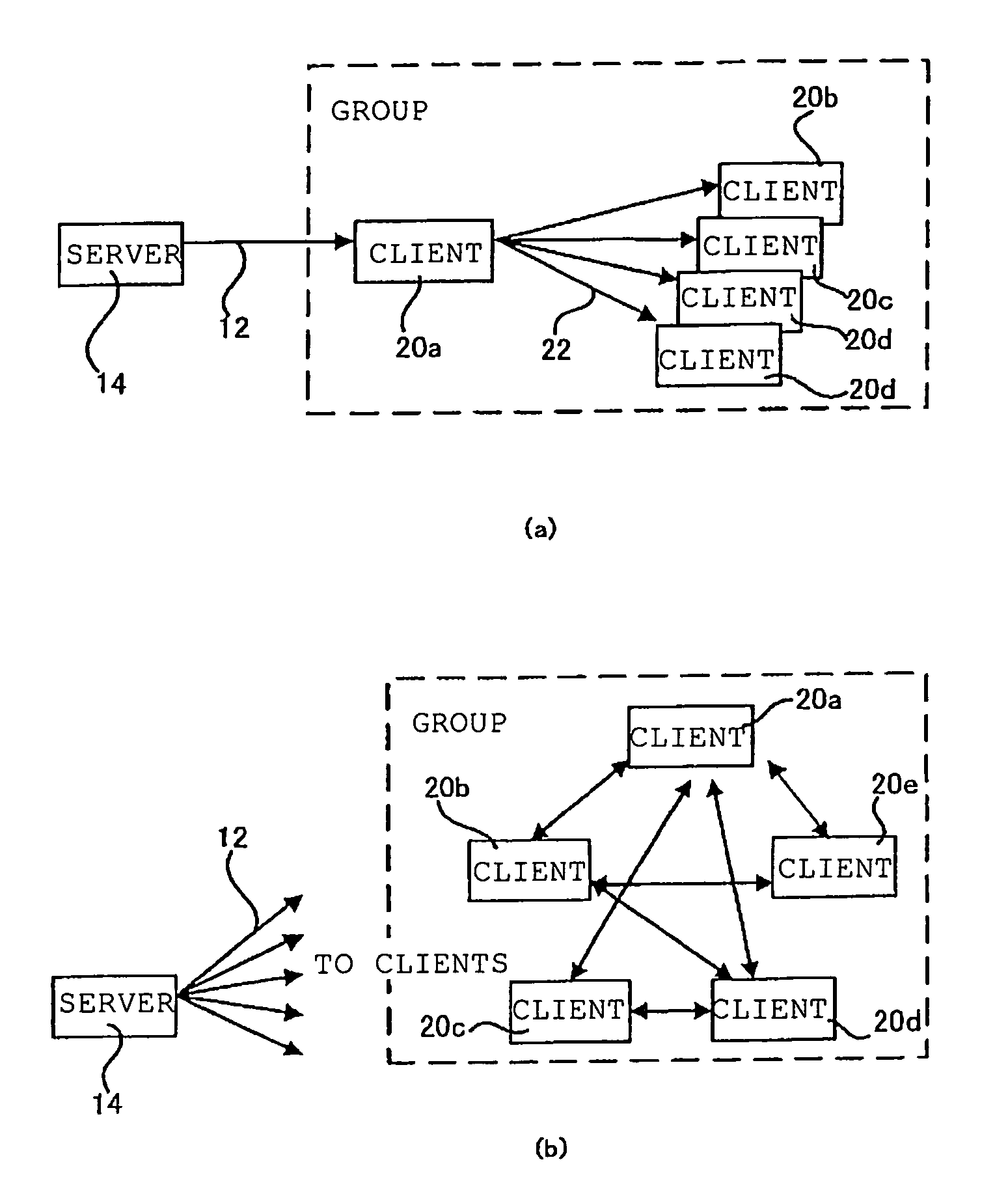
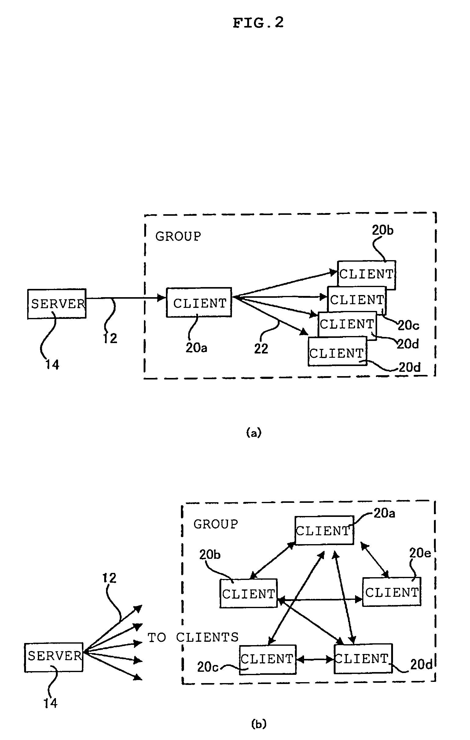
[0030]Furthermore, the present invention provides pseudo tunneling distribution for performing efficient distribution from the server to the predetermined wide area group no matter whether the tunnel for performing the distribution exists. The pseudo tunnel distribution in the present invention means a distribution system and a distribution method, which enable the same digital contents to be provided smoothly to the clients in the wide area group without causing a serious time lag just by distributing the minimum source packets required for reconstructing the digital contents from the server to the wide area group without any overlap. In the pseudo tunnel distribution in the present invention, the server distributes the packets to the clients belonging to the plurality of groups without any overlap. In the present invention, the plurality of clients construct groups, and the plurality of groups construct the wide area group. Moreover, the server is constructed to be capable of transmitting the packets to the entire wide area group, and selects clients to which the packets are to be transmitted from the wide area group for each time when the server transmits the packets. At least one client receives the source packets constructing the digital contents from the server. The server and the clients hold a client list of the clients constructing the wide area group. The client having received the source packets refers to source packet distribution data or a list of preallocated copy destinations, which is received together with the source packets. Then, the client distributes the copy of the source packets to other clients. By executing the above-described processing, all of the clients reconstruct the digital contents just enough.
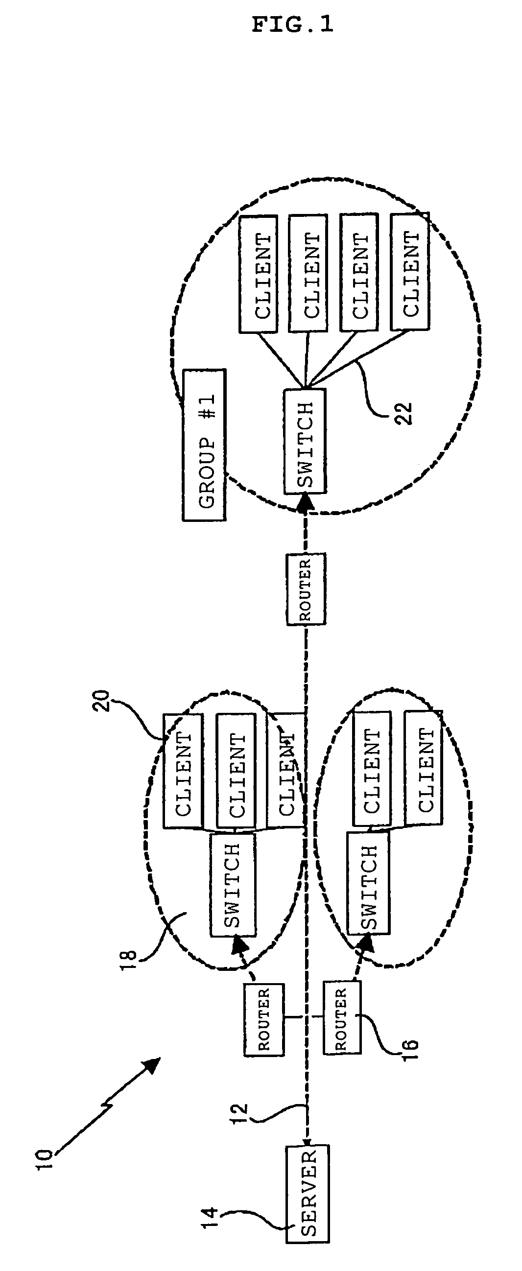
[0031]Furthermore, in the present invention, the LAN in the group is effectively used in order to make efficient use of network characteristics of the clients belonging to the wide area group. Each group is constructed by, for example, connecting the clients belonging to the group to one switching hub, thus enabling the communication using the function of the switch without affecting one another. Moreover, in the present invention, the third network corresponding to the multicast is constructed between an application computer and the plurality of clients connected under one router. Thus, the digital contents are shared in the group, and it is made possible to reduce the overheads of the clients and hardware resources.

Problems solved by technology

As illustrated in FIG. 31, the IP multicast method proposed by Deering, et at. has had a disadvantage in involving complicatedness of network resources, which includes a necessity of placing dedicated routers having “states” regarding clients receiving service instead of simple routers performing IP transfer though the method eliminates the overlap of the packets on the network 100 to enable good communication.
Another disadvantage in that scalability of the network is restricted has occurred, which includes a necessity of expansion of network equipment and incapability of coping with a situation such as sudden interference with and departure of the client in association with the above-described complicatedness of the network resources.
Moreover, because the IP multicast has a structure of sending data from an arbitrary source to an arbitrary group, the IP multicast has a disadvantage in weakening against a malicious attack and requiring a unique global address to be secured for the group.
However, the IP multicast is unsuitable for use in a backbone line of an enterprise, in which a slight line disconnection leads to a great loss, and use in moving picture distribution always requiring a fixed band to be secured.
As described above, the IP multicast has a disadvantage in that handling for securing reliability, avoiding congestion and securing security is difficult in comparison with unicast.
Furthermore, the IP multicast requires a large-scale change of a network infrastructure.
Because the server 108 executes the calculation that performs this reconstruction, there is a disadvantage in that an overhead given to the server 108 is increased.
This brings more and more complicatedness of the construction of the minimum network, and therefore, the overhead added to the server 108 in the reconstruction will be further increased.

Method used


Image

  • Digital content delivery system, digital content delivery method, program for executing the method, computer readable recording medium storing thereon the program, and server and client for it
  • Digital content delivery system, digital content delivery method, program for executing the method, computer readable recording medium storing thereon the program, and server and client for it
  • Digital content delivery system, digital content delivery method, program for executing the method, computer readable recording medium storing thereon the program, and server and client for it

Examples


second embodiment

[0221]FIG. 14 is a diagram illustrating the digital contents distribution system of the present invention. The digital contents distribution system illustrated in FIG. 14 is constructed by including the source server 64 for crating the digital contents, the drain server 66 held in the source server 64 and for extracting and holding digital data subjected to the streaming processing, and the groups G#1, G#2 and G#3 connected through the network 12. A construction is adopted, in which a client included in each group is selected as an intermediate node and distribute the digital contents in the group in accordance with the present invention.

[0222]FIG. 15 is a block diagram illustrating constructions of the source server 64 and one client, which are illustrated in FIG. 14. As illustrated in FIG. 15(a), the source server creates streamed digital contents from the created digital data by use of the source decoder 64a and the FEC encoder 64b. The created packets are transmitted to the drai...

third embodiment

[0243]FIG. 24(c) is a diagram illustrating the source packet 92 for use in the present invention. The embodiment illustrated in FIG. 24(c) is made for the case where the destinations of the copy packets are originally obvious and description thereof is not necessary. In this case, the client previously selects the copy destinations from the client list stored in the storage means such as a memory and a hard disk, and selects clients in other groups, which have addresses allocated in a range that is not overlapped with the other clients, thus making it possible to prepare the copy destination list. Moreover, in the case of distributing the copy packets in the group in the embodiment of FIG. 24(c), the distribution thereof can be performed by executing the broadcast communication in the group. Furthermore, in another embodiment, a construction can be previously adopted, in which the client transmits the copy packets to the other clients in the group, and transmits each copy of the rec...


PUM


Abstract

A system distributes digital contents through first and second networks and. A server is connected to the first network, and clients for receiving and displaying or reproducing the digital contents are connected to the second network. The server divides digital contents held therein into a plurality of packets, and transmits packets of a minimum unit for constructing the digital contents to the second network. The clients include storage for holding the digital contents therein by use of the packets of the minimum unit received from the server and packets received from other clients constructing the second network.

Description

CROSS REFERENCE AND PRIORITY[0001]This application filed under 35 USC 371, is cross-referenced with, and claims priority from, International Patent Application PCT / JP03 / 07093 filed on Jun. 4, 2003, and published in English with Publication No. WO 03 / 105421 on Dec. 18, 2003, under PCT article 21(2), which in turn claims priority of Japanese Application No. 2002-165014, filed on Jun. 6, 2002 and Japanese Application No. 2002-303850, filed on Oct. 18, 2002.BACKGROUND OF THE INVENTION[0002]The present invention relates to a distribution of digital contents. More specifically, the present invention relates to a digital contents distribution system and a digital contents distribution method, which distribute digital contents from digital contents distribution sites through networks, and make a plurality of clients store the digital contents therein, thus making it possible to distribute the digital contents efficiently through the networks. Moreover, the present invention relates to a pro...

Claims


Application Information

Patent Timeline
Patent Type & Authority Patents(United States)
IPC IPC(8): G06F15/16G06F17/00G06F17/30H04L12/18H04L47/43
CPCG06F17/30017H04L12/1854H04L67/42H04L45/121H04L45/16H04L45/04H04L12/1836G06F16/40H04L67/104H04L2012/5603G06F17/00H04L67/01G06F16/48
Inventor SHIMIZU, SHUICHINAKAMURA, TAIGA
Owner TAIWAN SEMICON MFG CO LTD
Why Eureka
Try Eureka