Heat exchanger arrangement

a technology of heat exchanger and heat exchanger, which is applied in the direction of sustainable transportation, mechanical equipment, machines/engines, etc., can solve the problems of drag penalty, drag to the main propulsive flow, and sizing also create drag penalty, so as to reduce static pressure

Inactive Publication Date: 2010-10-12
ROLLS ROYCE PLC
View PDF7 Cites 60 Cited by
  • Summary
  • Abstract
  • Description
  • Claims
  • Application Information

AI Technical Summary

Benefits of technology

[0006]In accordance with aspects of the present invention there is provided a heat exchanger arrangement for a gas turbine engine, the arrangement comprising a fluid flow presented to a heat exchanger at an inlet and the heat exchanger incorporated within a housing over wh

Problems solved by technology

In such circumstances the prior heat exchanger arrangement depicted in Prior Art FIGS. 1 and 2 has a number of disadvantages particularly in relation to increasing the temperature in the zone 11 between the housing incorporated in the heat exchanger 6 and surrounding parts of the engine as well as a necessary large vent exit area 12 to generate the desired pressure drop across the heat

Method used


Image

  • Heat exchanger arrangement
  • Heat exchanger arrangement
  • Heat exchanger arrangement

Examples


first embodiment

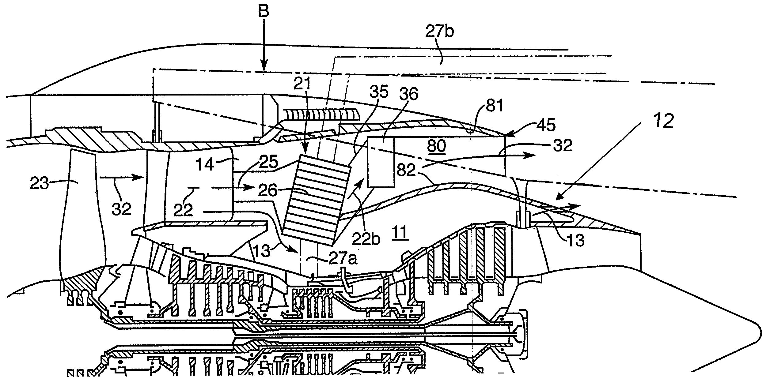
[0030]FIGS. 3 to 5 illustrate a heat exchanger arrangement 21 in accordance with aspects of the present invention. Thus, the arrangement 21 has a heat exchanger 26 to act as a pre-cooler for another fluid such as the ventilation air for the cabin of an aircraft. Conduits for that other cooled fluid are shown by broken lines 27a , 27b in FIG. 3. The heat exchanger 26 receives a coolant fluid flow 22 through an inlet 25. The regulating fan air valve, as with the previous arrangement depicted in prior art FIGS. 1 and 2 is not required and therefore removed. The heat exchanger 26 receives the coolant fluid flow 22 and exhausts that flow through ducting 35 to an outlet valve 36. This valve 36 is shown schematically in FIG. 3 and as more closely depicted in FIGS. 4 to 5 and extends into a by-pass fluid flow 32 in order to generate a reduction of static pressure and so suck coolant flow 22b through the heat exchanger 26.

[0031]By provision of a heat exchanger geometry and particularly in re...

second embodiment

[0042]Alternatively, a second embodiment in accordance with aspects of the present invention is depicted in FIGS. 6 to 9. In this embodiment, an elongated flap is utilised in order to again create a static pressure reduction to stimulate and regulate fluid flow through the heat exchanger. As previously, a compressor fan 53 provides a bypass fluid flow 52, part of which fluid flow 52a is presented to a heat exchanger 56 which in the embodiment depicted in FIGS. 6 to 9 also includes a fan air valve 55. As previously, the heat exchanger 56 exhausts an exhaust fluid flow 58 through a conduit 65 to a valve 66. The fluid flow through the heat exchanger 56 cools another flow generally comprising compressed air in a conduit 57 in order to act as cabin ventilation or de-icer flows for operations within an aircraft associated with an engine incorporating a heat exchanger arrangement 51 in accordance with aspects of the present invention. The outlet valve 66 is schematically depicted in FIG. 6...


PUM


Abstract

In certain circumstances recovery of a fluid flow presented through a heat exchanger into another flow can create problems with respect to drag and loss of thrust. In gas turbine engines heat exchangers are utilized for providing cooling of other flows such as in relation to compressor air taken from the core of the engine and utilized for cabin ventilation and de-icing functions. By providing an outlet valve through an outlet duct in a wall of a housing the exhaust fluid flow from the heat exchanger can be returned to the by-pass flow with reduced drag effects whilst recovering thrust. The valve may take the form of a flap displaceable into the by-pass flow before an exit plan to create a reduction in static pressure drawing fluid flow through the heat exchanger.

Description

CROSS-REFERENCE TO RELATED APPLICATIONS[0001]This application claims priority to GB 0607771.3, filed 20 April 2006 and currently issued under United Kingdom Patent No. 2,437,377.BACKGROUND OF THE INVENTION[0002]The present invention relates to heat exchanger arrangements and more particularly to heat exchanger arrangements utilised in gas turbine engines for cooling fluid flows such as with respect to ventilation air or oil within the engine or for de-icing.[0003]Operation of gas turbine engines is well known and incorporates significant fluid flows including compressed air provided by the compressor fans of that gas turbine engine. This compressed air flow is bled for a number of functional operations and in particular in order to provide through an appropriate heat exchanger cooling of other fluid flows such as the ventilation air in the cabin of an aircraft associated with a gas turbine engine or potentially with respect to fuel or lubricating oil coolers in the engine. The coola...

Claims


Application Information

Patent Timeline
IPC IPC(8): F02K99/00
CPCF02C7/141F02K3/06F02K3/115Y02T50/671Y02T50/675Y02T50/60F02C3/04F02C7/14F02K3/02
Inventor STRETTON, RICHARD GRICHARDS, MARTYN
Owner ROLLS ROYCE PLC
Why Eureka
Try Eureka