Shock absorber for the front or rear region of a railborne vehicle having at least one energy absorption device

a technology of energy absorption device and rear region, which is applied in the direction of bumpers, vehicular safety arrangments, transportation and packaging, etc., can solve the problems of insufficient adaptation to absorb or dissipate, the response of the energy absorption mechanism on the one hand and the sequence of events during energy absorption on the other hand, and the inability of the energy absorption mechanism to absorb full impact energy. , to achieve the effect of preventing the pivoting motion and increasing the impact for

Inactive Publication Date: 2010-10-12
VOITH PATENT GMBH
View PDF15 Cites 17 Cited by
  • Summary
  • Abstract
  • Description
  • Claims
  • Application Information

AI Technical Summary

Benefits of technology

[0040]If a horizontally-extending buffer plate preferably transverse to the vehicle longitudinal axis is used to bridge the clearance between the non-articulated end regions of the bumper bars, it is of advantage for a first end region of the buffer plate to be connected to the bumper bar of the first energy absorption device by means of a fourth bearing and, oppositely, a second end region of the buffer plate to the bumper bar of the second energy absorption device by means of a fifth bearing such that the impact force which occurs when an object collides for example frontally with the buffer plate, particularly the center region of the buffer plate, is transferred from the buffer plate to the two bumper bars through the end regions affixed to the respective bumper bars of the energy absorption devices and thus introduced into the two energy absorption devices of the shock absorber. Because the end regions of the buffer plate are respectively connected to the associated bumper bars by means of a bearing (fourth or fifth bearing), the buffer plate does not obstruct the pivoting movement of the bumper bars when the shock absorber is activated.
[0041]Providing a buffer plate to bridge the clearance between the non-articulated end regions of the bumper bars offers the additional advantage that also in the case of colliding side-ways with an obstacle, both energy absorption devices of the shock absorber will respond, in consequence of which the shock absorber is also suited to absorb higher impact forces. The buffer plate thereby effects that upon a pivoting of one of the two bumper bars about a pivot axis defined by its associated first bearing, the other bumper bar is also concurrently pivoted about the pivot axis defined by its own associated first bearing.
[0042]As already indicated, however, it is also conceivable that instead of utilizing a buffer plate coupled to the bumper bars of the energy absorption devices by means of a bearing, an, e.g., flexible element mounted between the non-articulated end regions of the bumper bars can be employed, for example a cable, a belt or a chain. Unlike with a relatively rigid buffer plate, it is not necessary when using a flexible element for same to be coupled to the bumper bars of the energy absorption devices by means of a bearing. Instead, the respective end regions of the flexible element can be fixedly connected to the buffer plate since the element used to bridge the clearance between the non-articulated end regions of the bumper bar is flexible and thus, does not hinder the pivoting motion simultaneously realized by the bumper bars upon a frontal collision.
[0043]The providing of a flexible element to bridge the clearance between the non-articulated end regions of the bumper bar can then be of particular advantage when activation of both energy absorption devices of the shock absorber is to be prevented upon a side-on collision with an obstacle.

Problems solved by technology

In other words, after the operating load of the regeneratively-designed energy-absorbing mechanism is exceeded, for instance when the vehicle impacts an obstacle (i.e., a crash), the regeneratively-designed energy-absorbing mechanism is usually too limited to absorb the full amount of resultant impact energy.
For example, should a deformation tube or a crash box be employed as an energy-absorbing mechanism, there is the risk—when non-axial forces are introduced into the deformation tube—of “seizing” or wedging and canting, with the result that the response of the energy-absorbing mechanism on the one hand and the sequence of events during energy absorption on the other are no longer predictable.
In such situations, in no way can this be deemed a frontal or substantially frontal collision.
Therefore, the problem on which the invention is based is that in terms of absorbing the impact energy which occurs upon a crash, the conventional solutions, for example known in rail vehicle technology and already effectively employed in regional transit or high-speed trains, are not or are at least not sufficiently suited to absorb or dissipate the impact energy occurring upon a non-axial and in particular side-on collision of the vehicle with an obstacle; i.e., pursuant a predictable sequence of events.

Method used


Image

  • Shock absorber for the front or rear region of a railborne vehicle having at least one energy absorption device
  • Shock absorber for the front or rear region of a railborne vehicle having at least one energy absorption device
  • Shock absorber for the front or rear region of a railborne vehicle having at least one energy absorption device

Examples


Embodiment Construction

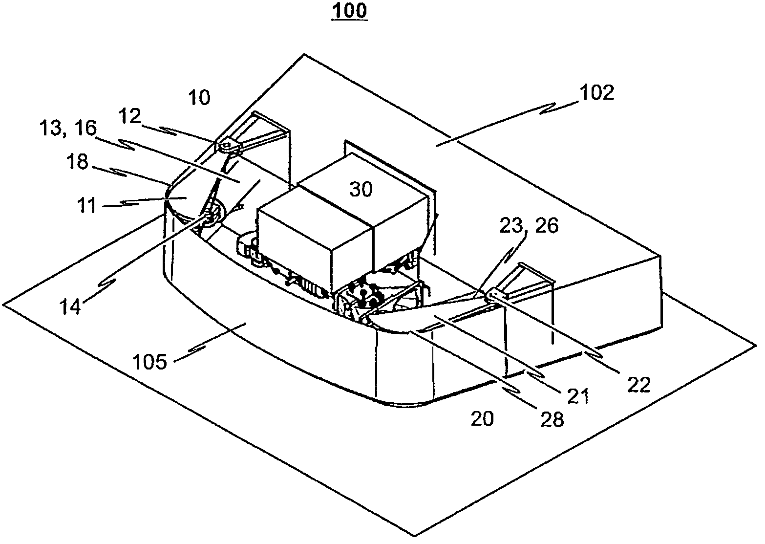
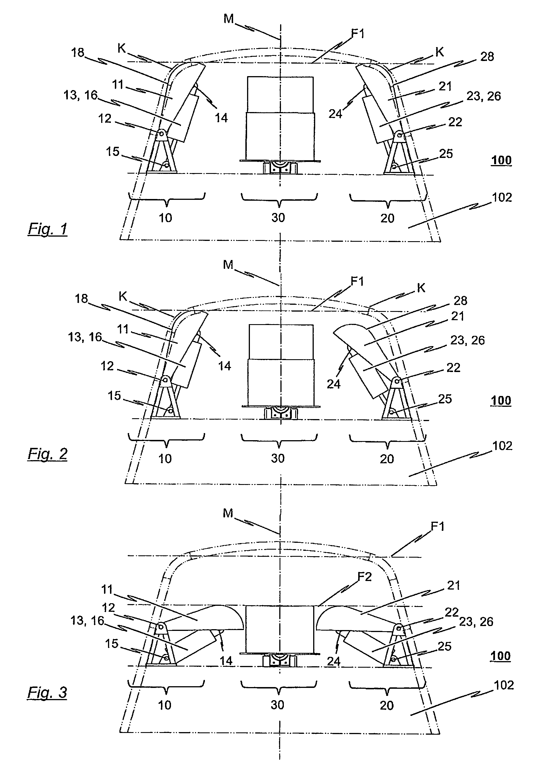
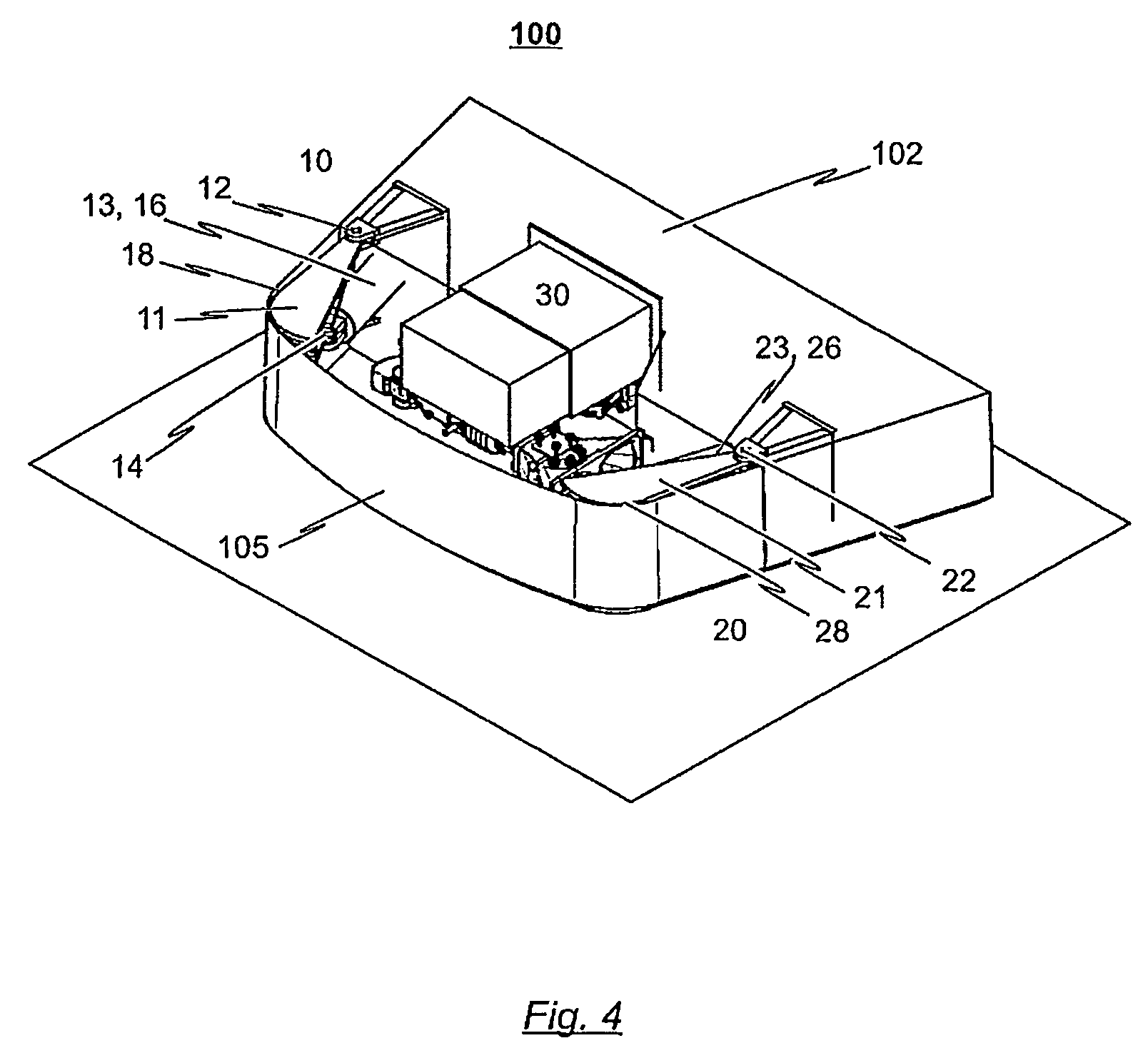
[0061]In the following, the structuring and functioning of a shock absorber 100 provided in the front or rear region of a railborne vehicle and including a first and a second energy absorption device 10, 20, in each case in accordance with a first embodiment of the invention, will first be described by drawing reference to the illustrations provided in FIGS. 1 to 3. The shock absorber 100 is, as depicted, arranged in a front or rear region of a railborne vehicle (not explicitly shown in detail), in particular a streetcar vehicle, and serves to at least partly absorb or dissipate the impact energy occurring upon the vehicle experiencing a frontal and / or side-on collision with an obstacle.

[0062]The energy absorption devices 10, 20 employed in the shock absorber 100 in accordance with the illustrations of FIGS. 1 to 3 are disposed at the front end of the railborne vehicle laterally distanced from the vertical center longitudinal axis M. In detail, a symmetrical arrangement of the two e...


PUM


Abstract

The invention relates to an energy absorption device as part of a shock absorber for the front or rear region of a railborne vehicle, in particular a streetcar vehicle, wherein the energy absorption device is designed to absorb or dissipate at least a portion of the impact energy which occurs when the vehicle impacts an obstacle. The invention includes a bumper bar which is pivotably connected to the vehicle underframe by a first bearing, a pendulum support connected to the bumper bar by a second bearing and to the vehicle underframe by a third bearing such that the bumper bar and pendulum support form a tripod. The resultant moment of force of the bumper bar pivoting about a pivot axis defined by a first bearing is introduced as linear force into the energy-absorbing mechanism and at least partly absorbed or dissipated there.

Description

CROSS-REFERENCE TO RELATED APPLICATIONS[0001]The present invention claims priority from European Patent Application No. 07 017 390.1, filed Sep. 5, 2007, the contents of which are herein incorporated by reference in their entirety.BACKGROUND OF THE INVENTION[0002]1. Field of the Invention[0003]The invention relates to an energy absorption device for a railborne vehicle, in particular a streetcar vehicle, wherein the energy absorption device is designed so as to absorb or dissipate at least part of the impact energy which occurs when the vehicle impacts an obstacle. The invention moreover relates to a shock absorber for the front or rear region of a railborne vehicle, in particular a streetcar vehicle, wherein the shock absorber includes at least one energy absorption device as noted above which is connectable to the vehicle underframe at the front or rear region of the vehicle.[0004]2. Description of the Related Art[0005]It is known to equip railborne vehicles such as track-borne ve...

Claims


Application Information

Patent Timeline
Patent Type & Authority Patents(United States)
IPC IPC(8): B61D15/06
CPCB60R19/14B60R19/26B61D15/06B61F19/04B60R19/34B61D17/06
Inventor MATTSCHULL, VOLKER
Owner VOITH PATENT GMBH
Why Eureka
Try Eureka