Method of removing excess metal from casting with press, and cutter used therefore

a technology of excess metal and casting, which is applied in the field of removing excess metal from casting with press, and the use of a cutter, can solve the problems of not being able to effectively remove the method is not effective for removing an excess metal the latter cannot be defined as an unnecessary portion of a casting, etc., to achieve the effect of reducing the cost of finishing the casting and high speed

Inactive Publication Date: 2010-10-12
MOHKA MFG
View PDF5 Cites 2 Cited by
  • Summary
  • Abstract
  • Description
  • Claims
  • Application Information

AI Technical Summary

Benefits of technology

[0017]According to the present invention, the excess metal can be removed from a casting with a press without using a machine tool. Especially, the excess metal of a work can be removed by punching it into various shapes. Therefore, the cost of finishing the casting can be reduced. Further, compared with a method in which the excess metal is removed with a machine tool, the finishing processing can be performed at high speed.

Problems solved by technology

Therefore, the latter can not be necessarily defined as an unnecessary portion of a casting.
In general, the larger the volumes of the excess metal portions are, the more difficult it becomes to remove the excess metal portions from the casting.
However, this method is not effectively used for removing an excess metal portion of a casting such as a portion of the casting which is provided for the design object, the volume of which is relatively large.
Therefore, it is unknown whether or not the capacity of removing an unnecessary portion from a casting, the volume of which is relatively large, is sufficiently large.
Accordingly, an excessively heavy load is given to the blade.
Therefore, it seems to be difficult that the cutting is conducted by a press.
However, when the machine tool is used, the man-hour is increased and the manufacturing cost is raised.
Further, when a new machine tool is used for finishing a casting, an excessive equipment investment is required.

Method used


Image

  • Method of removing excess metal from casting with press, and cutter used therefore
  • Method of removing excess metal from casting with press, and cutter used therefore
  • Method of removing excess metal from casting with press, and cutter used therefore

Examples


Embodiment Construction

[0063]Referring to an embodiment shown in the drawings, the present invention will be explained in more detail.

[0064]Structural Constitution

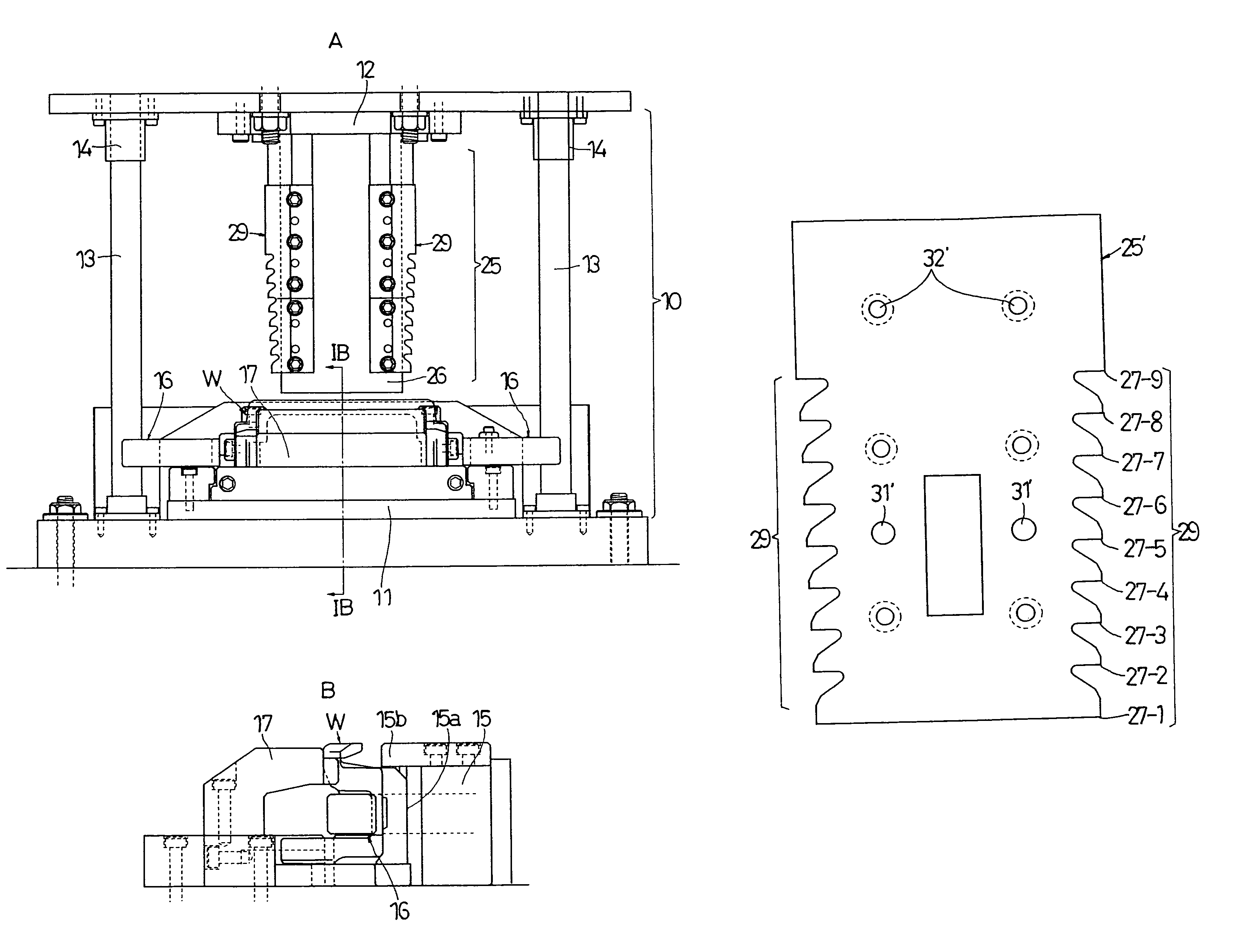
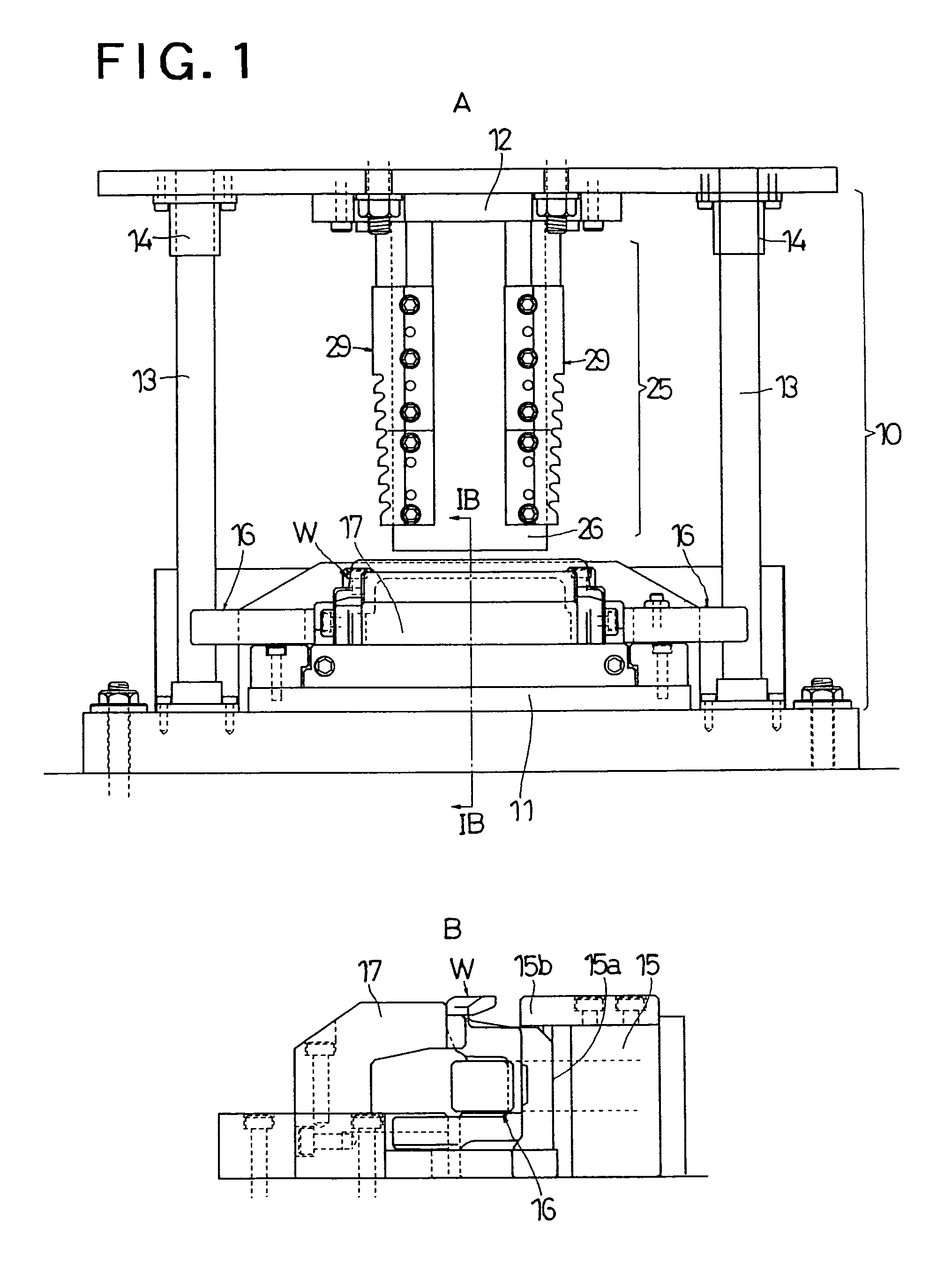
[0065]FIG. 1 is a view showing an example of the device 10 for removing excess metal from a casting which is used for executing a method of removing excess metal from a casting with a press according to the present invention. Reference numeral 11 is a stationary die (lower die) located in a lower portion, and reference numeral 12 is a movable die (upper die) located in an upper portion. The movable die 12 is elevated from the stationary die 11 by a necessary stroke being guided by the guide posts 13, 13 mounted on the stationary die 11. Reference numerals 14, 14 are guide bushes provided on the movable die side. Work W, which is a casting, is set on the lower die by the receiving clamp 15 located in the middle of the lower die, the right and left retracting type clamps 16, 16 and the holding clamp 17 located on the viewer's side in the drawing.

[...


PUM

PropertyMeasurementUnit
depthaaaaaaaaaa
depthaaaaaaaaaa
cutting depthaaaaaaaaaa

Abstract

A set of dies are composed in order to remove excess metal from a casting with a press. A method of removing the excess metal from the casting includes the steps of: attaching a cutter to one of the stationary die side or the movable die side; setting a work on the other side; and punching excess metal of the work into a recess shape by one punching motion of the movable die with a plurality of blades from the first blade, which is smaller, to the final blade, which is larger and protruded, when the excess metal of the work is removed by a punching motion of the movable die conducted on the stationary die.

Description

TECHNICAL FIELD[0001]The present invention relates to a method of removing excess metal from a casting with a press and also relates to a cutter used therefore.BACKGROUND ART[0002]A casting has unnecessary portions to be removed such as a pouring gate, a weir, burr and so forth. These unnecessary portions are removed in the finishing process. In order to remove these unnecessary portions, it is conventional to conduct punching on these portions with a hydraulic press or mechanical press to which a cutting blade is attached. Concerning the excess metal of a casting, there are two types. One is the excess metal of a casting which is unavoidably generated in the process of casting, and the other is the excess metal of a casting which is intentionally provided for accomplishing a predetermined design object. Therefore, the latter can not be necessarily defined as an unnecessary portion of a casting. However, in the present invention, irrespective of the cause of the generation of the ex...

Claims


Application Information

Patent Timeline
Patent Type & Authority Patents(United States)
IPC IPC(8): B22D31/00
CPCB22D17/2076B22D31/00
Inventor NISHINA, KATSUYA
Owner MOHKA MFG
Why Eureka
Try Eureka