Belt lifter apparatus

a belt lifter and belt technology, applied in the direction of lifting devices, loading/unloading, transportation and packaging, etc., can solve the problems of increasing the downward force on the belt lifter, affecting the lifting effect of the belt lifter, so as to achieve convenient portability, increase the lifting force, and increase the vertical lift

Active Publication Date: 2010-10-12
FLEXIBLE STEEL LACING
View PDF3 Cites 15 Cited by
  • Summary
  • Abstract
  • Description
  • Claims
  • Application Information

AI Technical Summary

Benefits of technology

[0005]In accordance with a preferred form of the present invention, a light-weight and easily portable belt lifter is provided for raising tensioned conveyor belts, and particularly belts that are troughed, through a greater vertical lift and / or with increased lifting force than the previously described commercial belt lifters. By way of example only, the preferred belt lifter described hereinafter can provide about a 60% increase in lifting height over the current belt lifters. Additionally, the lifting force for this embodiment is rated at 4000 pounds verses the approximately 2300 pound capacity for prior belt lifters.
[0008]In accordance with another form, the fixed ends of the lifting arms of the scissors mechanism are located at positions on the belt lifter such that at the greatest lift height, the translatable pivot axis is substantially centered beneath the lateral center of the belt with the upper ends of the lever arms being equally laterally spaced from the centerline of the belt. Thus, the belt load is centered on the belt lifter, and each side of the belt is being raised through equal distances thereby providing stability against tilting or rollover of the belt lifter.
[0009]In accordance with another aspect, the belt lifter has light-weight tubular supporting members which are adapted so that the belt lifter apparatus is adjustable in its width to suit different spans of conveyor frame supports on which the belt lifter is placed under the upper run of the conveyor belt. In this form, the support members may be a pair of telescoping tubular members which provides a smaller overall size for the belt lifter when the telescoping members are retracted inwardly and which allows the telescoping members to be pulled outwardly to the size desired to span conveyor frame supporting members.
[0012]In accordance with another form, the belt lifting member is provided with adjustable wing arms of increased strength to support the inclined, trough forming sides of the belt during the belt lifting operation. This is achieved by providing adjustable braces that extend downwardly from an intermediate location along the length of the inclined wing arms to an end portion of the belt lifting member. Preferably, the braces, a portion of the wing arm, and the end portion of the belt lifting member form a strong triangularly shaped support or gusset for supporting the load to be applied to each wing arm. The braces may be pivoted at each of several different locations on upper ends to the wing arm and at lower ends to the end portion of the lifting member to provide a braced support for the wing arms at each of several angles thereby allowing positioning of the wing arms at substantially the same inclination as the particular inclination of the respective belt troughed portions to be lifted.

Problems solved by technology

The replacement of a conveyor roller is a difficult task in that the conveyor belts that need to be lifted off of rollers are usually troughed and tensioned and may be quite wide, for example 60 inches in width, and may also be on an incline.
Providing additional vertical lift is difficult in that the belt tension and therefore the downward force exerted on the belt lifter increases substantially for each inch beyond the current 10 inch lift provided by commercial belt lifters.

Method used


Image

  • Belt lifter apparatus
  • Belt lifter apparatus
  • Belt lifter apparatus

Examples


Embodiment Construction

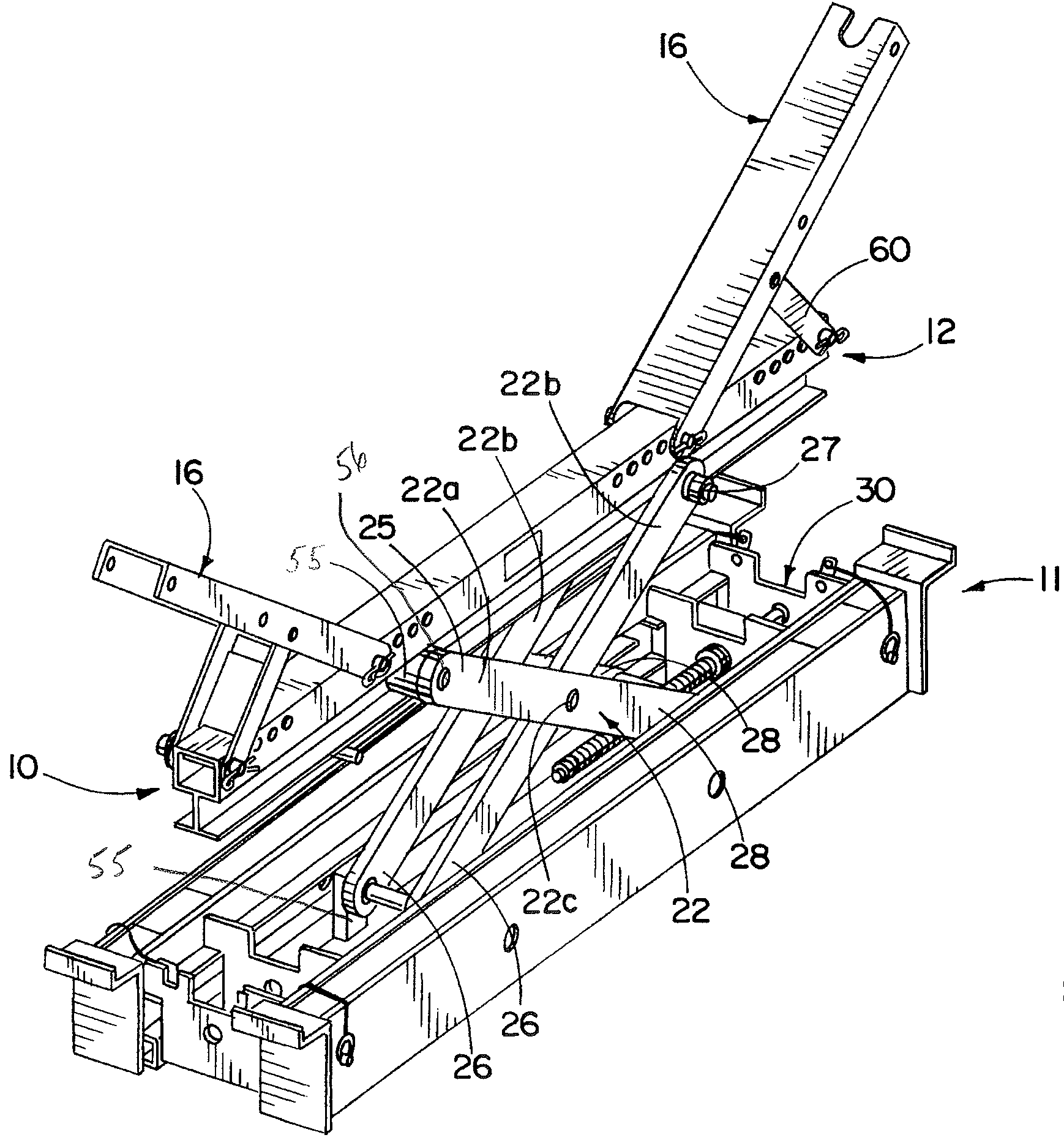
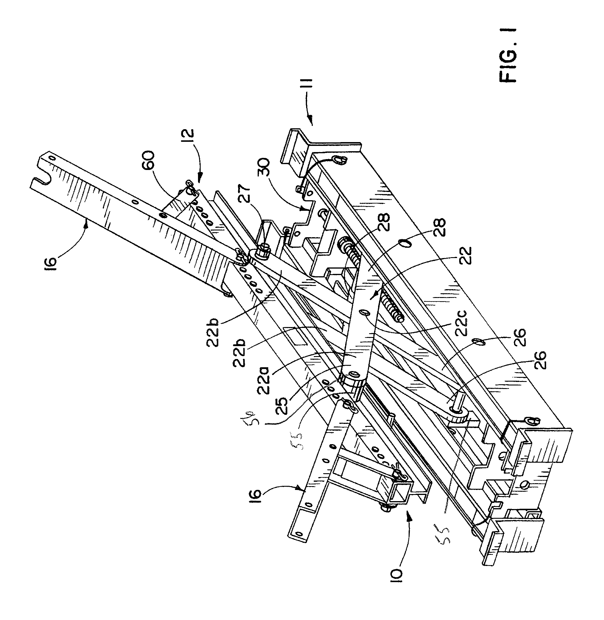
[0026]As shown in the drawings for purposes of illustration, the belt lifting apparatus 10 (hereinafter called “the belt lifter”) is shown in FIG. 1 as comprising a lower support element or base member 11 which is adapted to be mounted on the conveyor frame and a upper support member 12 which is to be positioned under the troughed belt 14 (FIG. 12) or flat belt for lifting the belt vertically upward for the typical purposes of roller repair or for forming of a splicing station. A pair of adjustable, inclined support lifting, wing arms 16 at end portions 12b of the upper support member 12 engage and lift inclined troughed belt from the inclined side rollers 18, and a central portion 12a of the upper support member 12 lifts the central belt portion from the central rollers, as best seen in FIG. 12. Usually the belt lifter will be in a troughed belt configuration such as shown in FIG. 1 wherein the inclined lifting, wing arms 16 are at an incline to the central portion 12a of the upper...


PUM


Abstract

In one form, a belt lifter apparatus provides increased lifting force and belt lift height by a scissors mechanism having crossed lifting arms each having a translatable end and having a translatable pivot axis between the lifting arms. Preferably, other ends of the lifting arms are fixed to an upper belt lifting member and to a lower support base member at locations such that the pivot axis translates to a position located substantially at the center of the lifted belt when the belt is lifted to the highest lift height. Lightweight, aluminum tubular members are used for the lifting member and the base support and each includes a track for supporting the translatable ends of the lifting arms. The span width of the base member is adjusted by sliding telescoping, tubular legs within the base tubular element. Pivoted wing arms are supported by braces extending to the belt lifting member.

Description

FIELD OF THE INVENTION[0001]This invention relates to an apparatus for lifting conveyor belts and more particularly to an apparatus for lifting tensioned conveyor belts usually for replacement of a roller located beneath the belt or to allow splicing of the belt or a repair of a rip or a tear in the belt.BACKGROUND OF THE INVENTION[0002]The replacement of a conveyor roller is a difficult task in that the conveyor belts that need to be lifted off of rollers are usually troughed and tensioned and may be quite wide, for example 60 inches in width, and may also be on an incline. For this purpose, a belt lifter often has to be placed on the supporting frame for the conveyor within a confined space. While current belt lifters lift the belt as much as ten inches, it would be desirable to lift the belt higher than ten inches to provide adequate space for easy removal of a conveyor belt roller, for instance. Because the conveyor belt lifters are used in the field for relatively large troughe...

Claims


Application Information

Patent Timeline
Patent Type & Authority Patents(United States)
IPC IPC(8): B66F3/08
CPCB65G15/00
Inventor DEVRIES, BRETT EDWIN
Owner FLEXIBLE STEEL LACING
Why Eureka
Try Eureka