
Sanitary fitting comprising an assembly of several light sources

a technology of sanitary fittings and light sources, applied in the direction of domestic plumbing, light and heating equipment, construction, etc., can solve the problem of mixing over a relatively large spatial area

Inactive Publication Date: 2010-10-12
HANSA METALLWERKE AG
View PDF13 Cites 12 Cited by
  • Summary
  • Abstract
  • Description
  • Claims
  • Application Information

AI Technical Summary

Benefits of technology

[0006]The inventors have recognised that currently used light sources, such as for example low-voltage halogen lamps as well as LEDs, which are particularly advantageous on account of their compactness, radiate the light over a relatively large spatial angular region. This makes it difficult on the one hand to mix over a relatively large spatial region the coloured light generated by the light sources and in this way to generate a mixed colour that is perceived as pleasant.
[0007]Secondly, so much light is radiated laterally by known light sources that basically only a region in the immediate vicinity of the inlet or outlet of the sanitary fitting is illuminated. If the light generated by the light sources is on the other hand focussed and mixed according to the invention by means of a collecting optics, then a water jet issuing from the sanitary fitting can be illuminated over a longer path—preferably from the inside to the outside—with a relatively more uniform colour, which results in an aesthetically very pleasing light effect.
[0008]Preferably the collecting optics comprises several optical elements having a collecting action, exactly one or also several of the optical elements being associated with each light source. In this way the light generated by the light sources can be detected and focussed very much more easily than would be the case with a single optical element, which detects collectively all light beams generated by the light sources.
[0011]A tilting of the light beam generated by the at least one light source is produced by such a parallel staggering of the radiation axes of the light sources relative to the symmetry axes of the associated optical elements. Due to the relative position of the radiation axis of the at least one light source relative to the symmetry axis of the associated optical element, the alignment and the degree of tilting can thereby be adjusted practically as desired. This opens up the possibility, simply through this tilting action, of aligning the light beams generated by the light sources onto a point lying outside the sanitary fitting, in the vicinity of which the light beams mix practically completely. In this way a complicated tilting arrangement of the light sources can be dispensed with.
[0012]Since the light sources on the one hand are spaced relatively close to one another and the aforementioned point may be located relatively far, for example about 50 cm, from the sanitary fitting, a very good intermixing of the light beams generated by the light sources is also achieved at relatively large distances from the said point. In this way the user of the sanitary fitting perceives a largely homogenous colour effect over the typically necessary length, which is determined by the distance between the sanitary fitting and an object, for example a washstand or a shower basin.
[0018]The optical collecting element preferably has an axis of symmetry that runs along the common axis of symmetry of the light sources. An aspherical effect is generally advantageous also with the optical collecting element.

Problems solved by technology

This makes it difficult on the one hand to mix over a relatively large spatial region the coloured light generated by the light sources and in this way to generate a mixed colour that is perceived as pleasant.
Secondly, so much light is radiated laterally by known light sources that basically only a region in the immediate vicinity of the inlet or outlet of the sanitary fitting is illuminated.

Method used


Image

  • Sanitary fitting comprising an assembly of several light sources
  • Sanitary fitting comprising an assembly of several light sources
  • Sanitary fitting comprising an assembly of several light sources

Examples


Embodiment Construction

[0028]While this invention is susceptible of embodiment in many different forms, there is shown in the drawings and will herein be described in detail one or more embodiments with the understanding that the present disclosure is to be considered as an exemplification of the principles of the invention and is not intended to limit the invention to the embodiments illustrated.

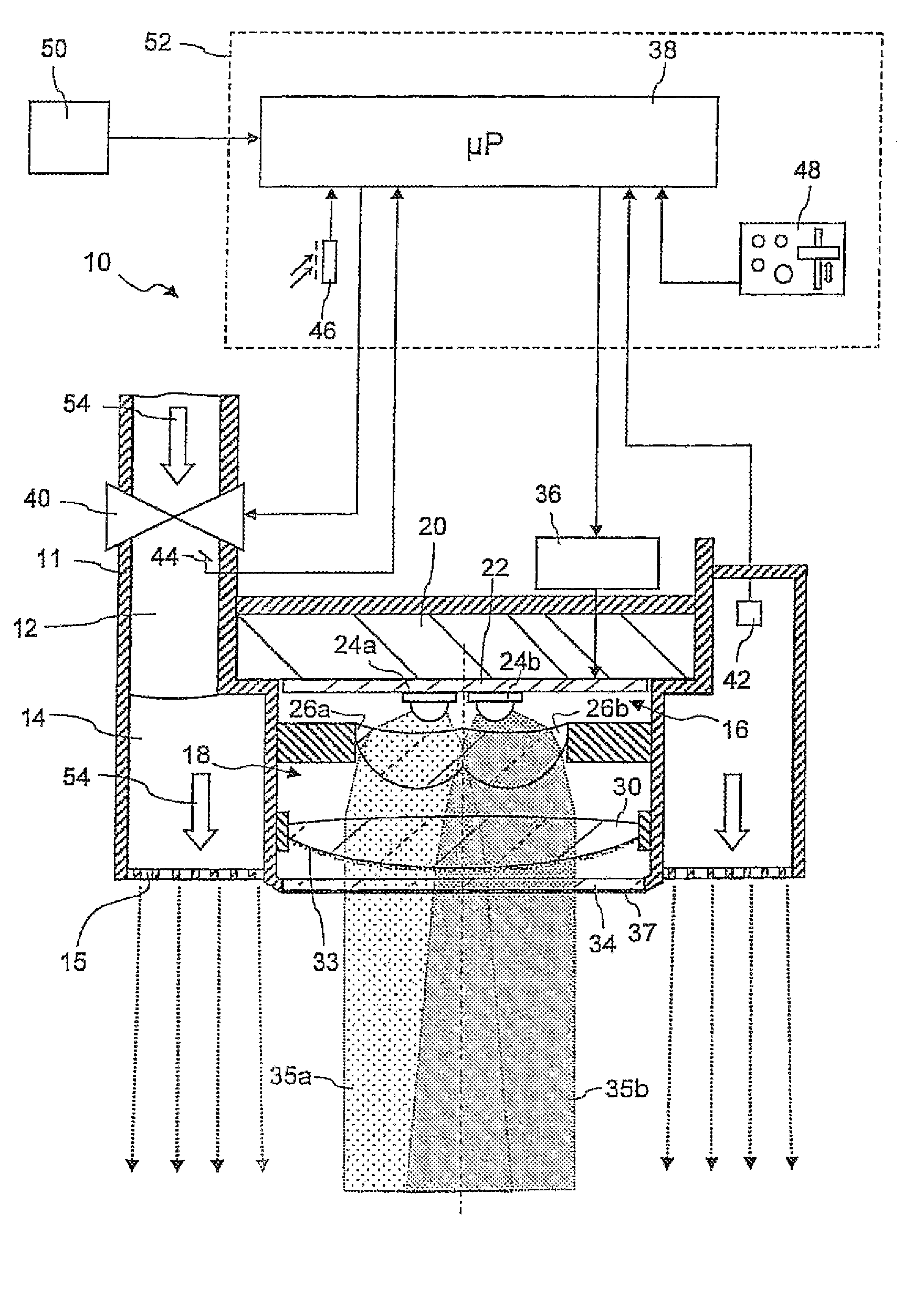
[0029]FIG. 1 shows in a diagrammatic axial section an outlet head 10 of a sanitary fitting, which is firmly installed in the sanitary area or may also be part of a handpiece. The sanitary fitting may for example be a shower fitting, a washstand fitting or a bath fitting. The outflow head 10 has a housing 11 and a mixing water outflow 12 contained therein, which is connected in a manner known per se to a mixer unit (not shown in FIG. 1). The mixer unit is for its part connected to a hot water source and a cold water source. The mixing water outflow 12 transforms into an annular duct 14, which is provided on the fr...


PUM


Abstract

The invention relates to a sanitary fitting containing an assembly of several light sources for illuminating water that flows out of or into the sanitary fitting, said light sources generating light of different colors. According to the invention, collecting optics are positioned upstream of the light sources to focus and mix the light that is generated by the light sources. This permits the generation of intensive mixed colors, which, for example, can illuminate the interior of a shower jet.

Description

RELATED APPLICATIONS[0001]This application claims the filing benefit of PCT Patent Application No. PCT / EP2005 / 013845, filed Dec. 22, 2005; which claims the benefit of German Patent Application No. 10 2005 001 305.8, filed Jan. 5, 2005; the contents of these applications all are incorporated herein by reference.TECHNICAL FIELD[0002]The present invention relates to a sanitary fitting comprising an assembly of several light sources for illuminating water that flows out of or into the sanitary fitting, wherein light of different colours can be generated by the said light sources.BACKGROUND OF THE INVENTION[0003]Such a sanitary fitting is known from DE 203 17 375 U1. The sanitary fitting described there comprises in the region of the water outlet or water inlet illumination means with which light of different colours can be generated. In this case the colour is adjusted depending on the temperature of the water. In an embodiment described in more detail therein the illumination means com...

Claims


Application Information

Patent Timeline
IPC IPC(8): F21V21/00
CPCE03C1/04F21V5/008F21V13/02F21V3/049E03C2001/0418F21V33/004F21Y2101/02F21Y2113/005F21Y2115/10F21Y2113/13
Inventor KUNKEL, HORSTVEIGEL, GUNTER
Owner HANSA METALLWERKE AG
Learn More