Stator of electric rotating machine and electric rotating machine

a technology of electric rotating machines and rotating machines, which is applied in the direction of dynamo-electric machines, ac commutators, dynamo-electric components, etc., can solve the problems of insufficient cooling of the rotating machine, and achieve the effect of less performance degradation and excellent cooling performan

Active Publication Date: 2010-10-12
DENSO CORP
View PDF11 Cites 22 Cited by
  • Summary
  • Abstract
  • Description
  • Claims
  • Application Information

AI Technical Summary

Benefits of technology

[0016]According to the present invention, there is provided a stator of an electric rotating machine and an electric rotating machine having a stator, which have excellent performance in cooling the turn portions of the stator, and accordingly, have less performance degradation due to overheat of the turn portions.

Problems solved by technology

However, the electric rotating machine having such a structure has a problem in that a coolant such as ATF for cooling the stator does not sufficiently penetrate into the turn portions, causing the stator winding to be insufficiently cooled.

Method used


Image

  • Stator of electric rotating machine and electric rotating machine
  • Stator of electric rotating machine and electric rotating machine
  • Stator of electric rotating machine and electric rotating machine

Examples


Embodiment Construction

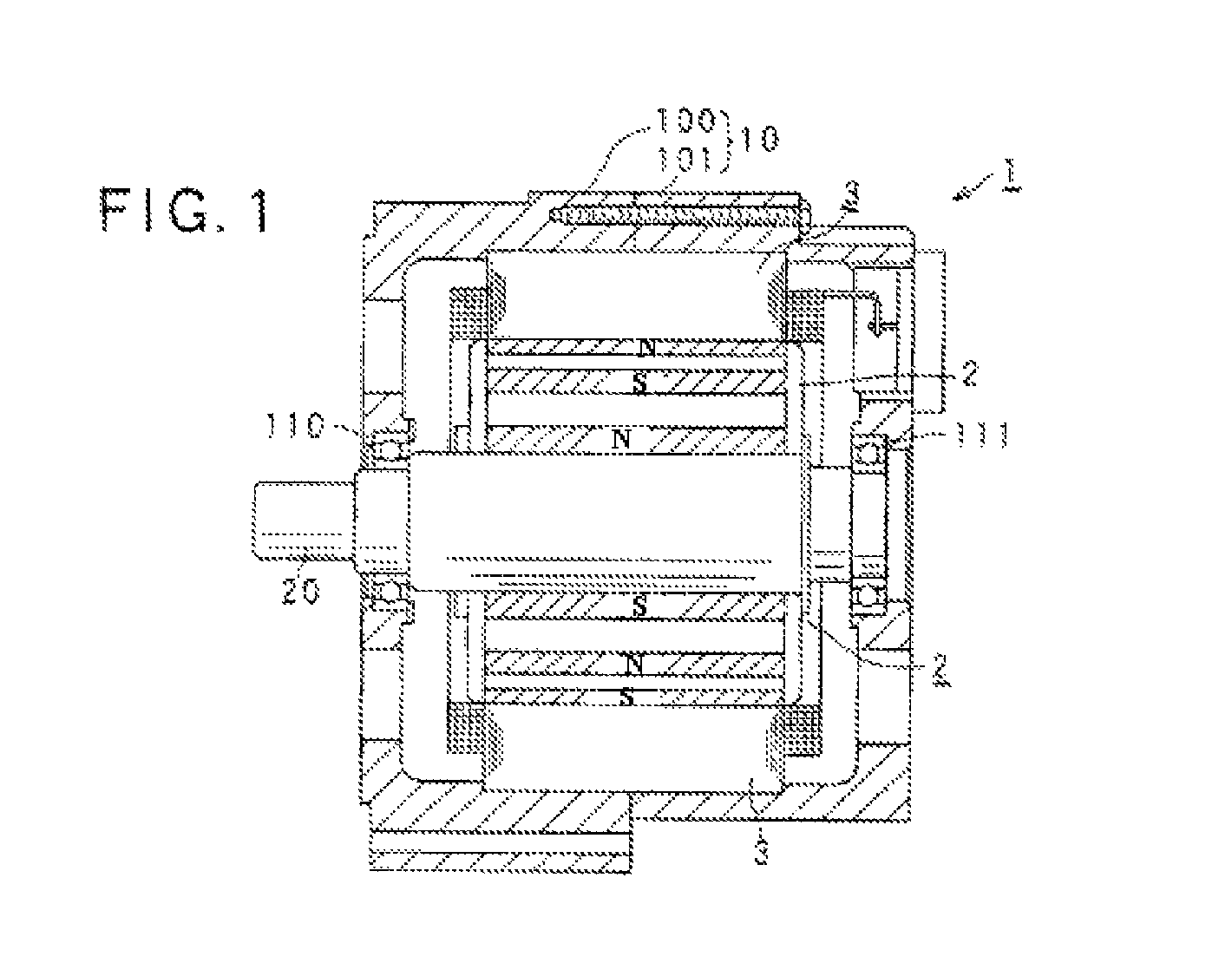
[0028]FIG. is a diagram showing a structure of an electric rotating machine 1 according to an embodiment of the invention. As shown in this figure, the electric rotating machine 1 includes a housing 10 constituted by a pair of housing members 100 and 101 each having a bottomed tubular shape and joined to each other at their opening portions, a rotor 2 fixed to a rotating shaft 20 rotatably supported by the housing 10 through bearings 110 and 111, and a stator 3 fixed to the housing 10 so as to surround the rotor 2 inside the housing 10.

[0029]The rotor 2 is provided with a plurality of magnet poles (S poles and N poles) formed in the outer periphery of the rotor 2 facing the inner periphery of the stator 3, such that different poles alternate in the circumferential direction of the rotor 2. In this embodiment, an 8-pole (four N poles and four S poles) rotor is used as the rotor 2.

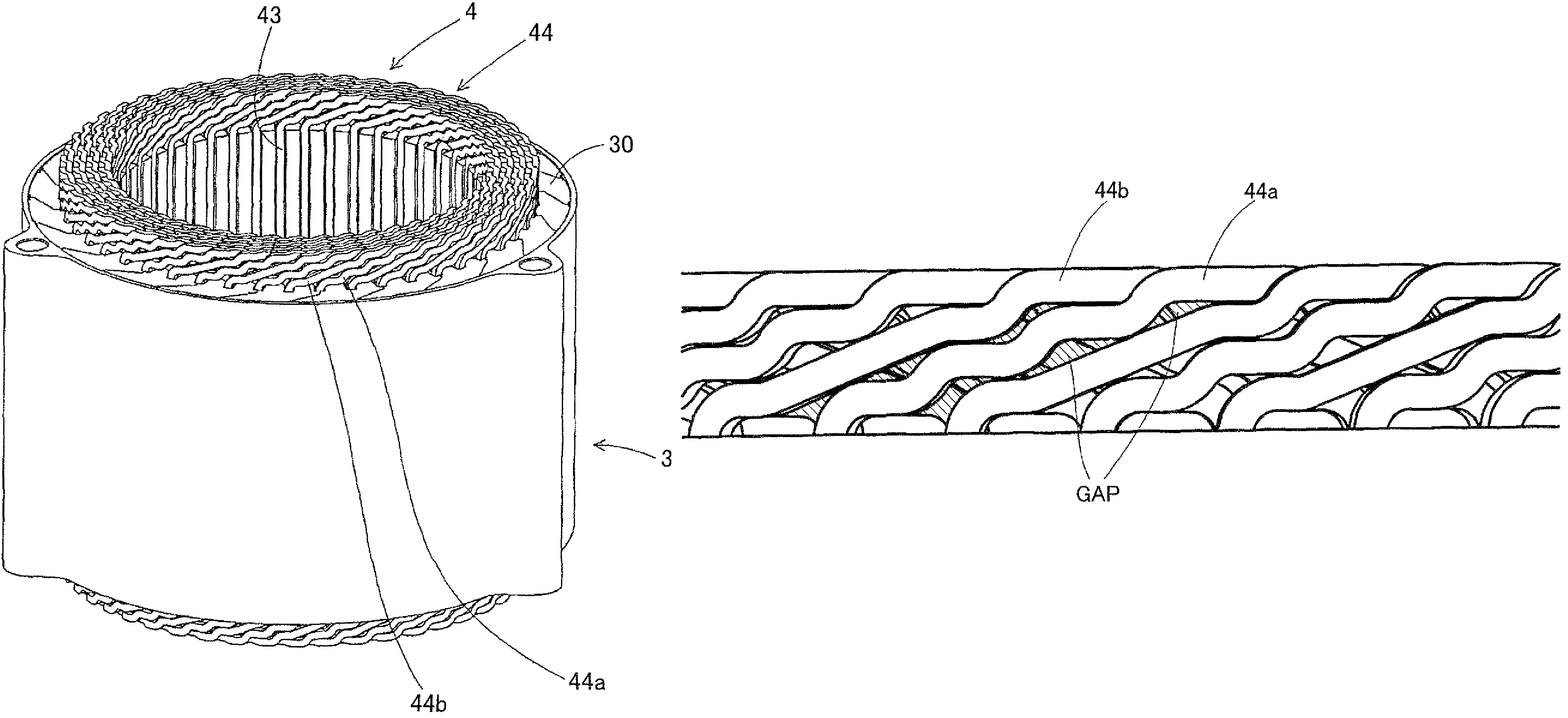
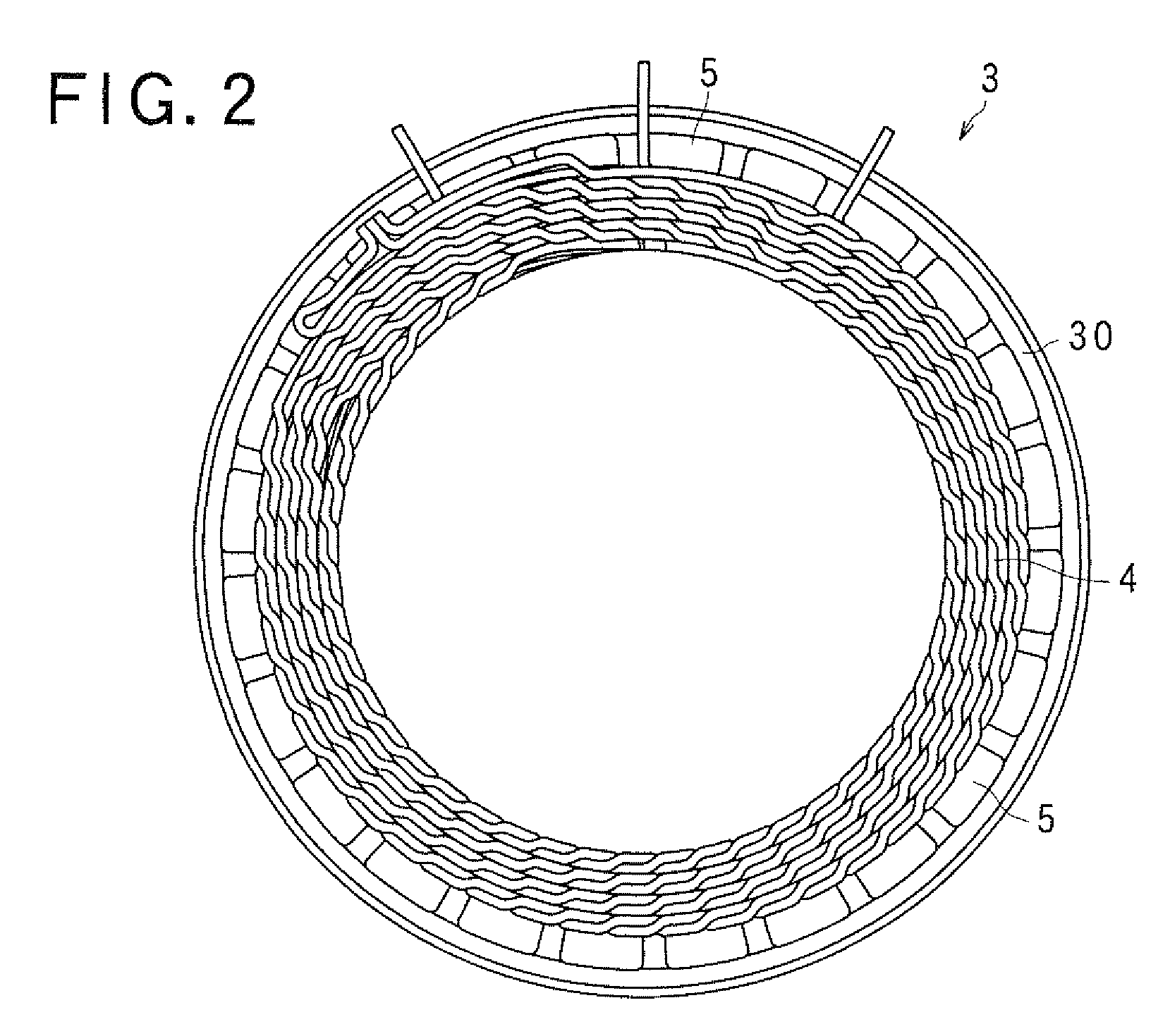
[0030]As shown in FIG. 2, the stator 3 includes a stator core 30, a three-phase stator winding 4 constitu...


PUM


Abstract

The stator of an electric rotating machine includes a stator core having slots formed therein along a circumferential direction thereof, and a stator winding formed by conductive wires wound on the slots. The stator winding includes in-slot portions accommodated in the slots and turn portions each of which connects each adjacent two of the in-slot portions outside of the slots. Each of the turn portions includes a first turn portion formed with M1 steps (m1 being a positive integer) extending along axial ends of the stator core, and a second turn portion formed with m2 steps (m2 being an integer larger than m1) extending along the axial ends.

Description

CROSS-REFERENCE TO RELATED APPLICATION[0001]This application is related to Japanese Patent Application No. 2008-110789 filed on Apr. 21, 2008, the contents of which are hereby incorporated by reference.BACKGROUND OF THE INVENTION[0002]1. Field of the Invention[0003]The present invention relates to a stator of an electric rotating machine, and an electric rotating machine having the stator.[0004]2. Description of Related Art[0005]In recent years, there is a growing need of electric rotating machines usable as electric motors or generators which are compact in size and of high quality.[0006]For example, an electric rotating machine mounted on a vehicle is required to generate more output power because of increase of vehicle loads, although the space assigned to mount the electric rotating machine in an engine compartment is becoming smaller.[0007]To meet the requirement, it is necessary to reduce the resistance of the phase windings of an electric rotating machine, increase the lamina...

Claims


Application Information

Patent Timeline
Patent Type & Authority Patents(United States)
IPC IPC(8): H02K3/04H02K3/12H02K3/34
CPCH02K3/12
Inventor KOUDA, SHINJI
Owner DENSO CORP
Why Eureka
Try Eureka