
Apparatus for monitoring non-linear distortions of radio signals and a method therefor

a radio signal and non-linear distortion technology, applied in the field of apparatus for monitoring non-linear distortion of radio signals, can solve the problems of inability to distinguish between the imbalance of the transmit site modulator and the feedback part, and suffer from imbalance, so as to achieve precise monitoring of non-linear distortion, low rate, and effective elimination of imbalances

Active Publication Date: 2010-10-12
TELEFON AB LM ERICSSON (PUBL)
View PDF6 Cites 7 Cited by
  • Summary
  • Abstract
  • Description
  • Claims
  • Application Information

AI Technical Summary

Benefits of technology

The present invention provides a front-end unit for a radio signal transmitter that can effectively compensate for non-linear distortions caused by the analogue modulator. The front-end unit includes a mixer, analog-to-digital converter, digital filter, and adaptive digital filter. The invention also provides a method for monitoring non-linear distortions and a transceiver for transmitting and receiving radio signals. The technical effects of the invention include improved signal quality, reduced distortion, and improved monitoring of non-linear distortions.

Problems solved by technology

Although analogue modulators can be used for wide bandwidth signals, they always suffer from imbalances.
The problem with compensation of the imbalances of the modulator is that when the feedback-signal is down-converted into baseband it is impossible to distinguish between the imbalances of the transmit site modulator and the feedback part.
This leads to a situation that for radio signal transmitters operating on a wide bandwidth it is necessary to use analogue and imbalanced modulators and digital modulators (balanced modulation) can be used only in transmitters operating on a small bandwidth.

Method used


Image

  • Apparatus for monitoring non-linear distortions of radio signals and a method therefor
  • Apparatus for monitoring non-linear distortions of radio signals and a method therefor
  • Apparatus for monitoring non-linear distortions of radio signals and a method therefor

Examples


Embodiment Construction

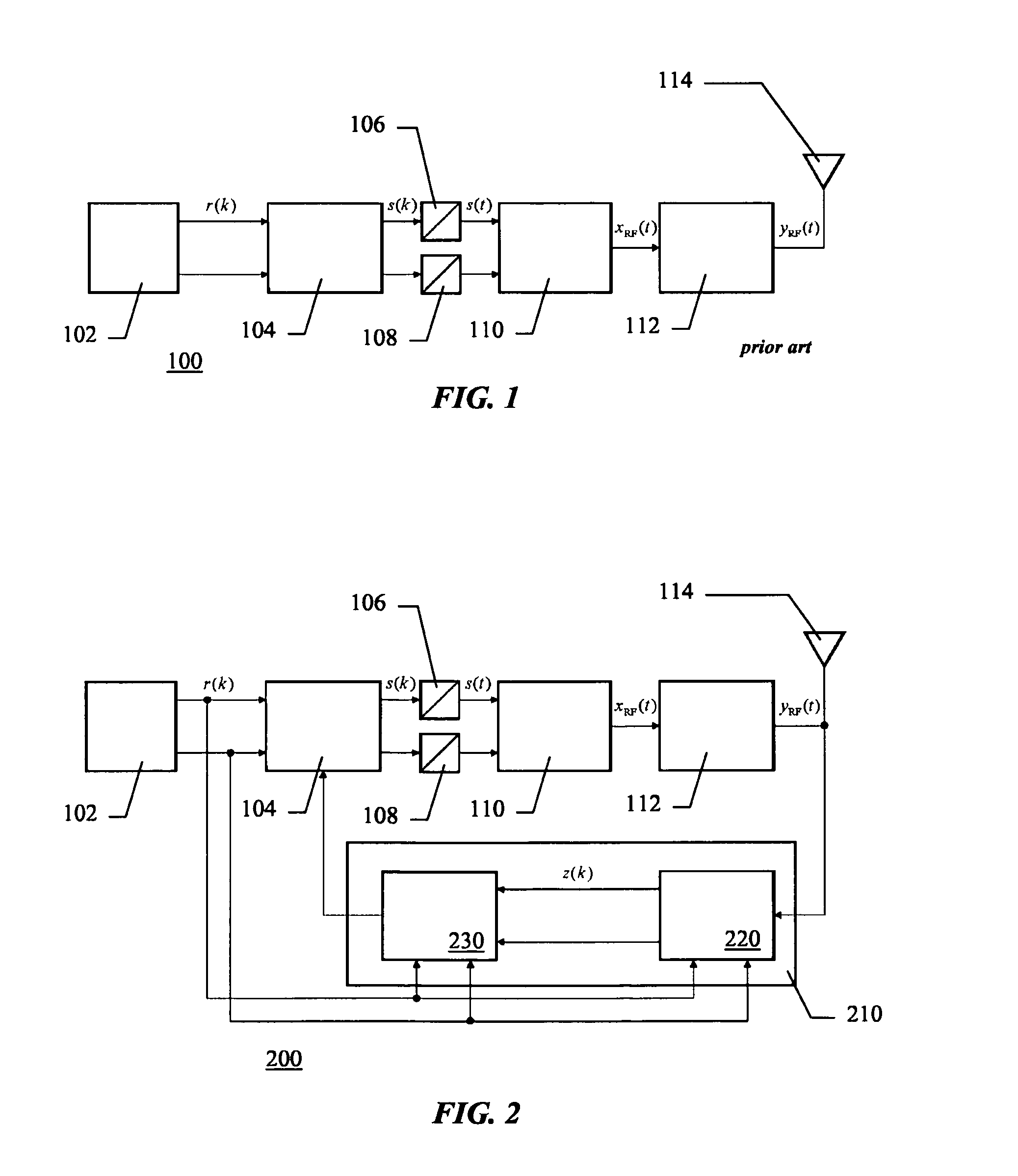
[0023]With reference to FIG. 2 a diagram illustrating a radio transmitter 200 in one embodiment of the present invention is presented. As in the solution known in the prior art the transmission path of the transmitter (or the transmitter part of a transceiver) comprises a digital signal source 102, which generates the information bearing signals in the baseband domain, (i.e. the in-phase-signal and the quadrature-signal), a compensation unit 104 for compensating the non-linear distortions, two digital-to-analogue converters (DACs) 106 and 108, one for the in-phase-signal and one for the quadrature-signal, an analogue modulator 110, to modulate the baseband signal onto a radio frequency (RF) carrier and an amplifier 112. The radio signals are transmitter via antenna 114 connected to the amplifier 112.

[0024]The compensation unit 104 is a parametric digital device; perfect compensation is only achieved, if suitable compensation-parameters are chosen. Since these parameters are dependan...


PUM


Abstract

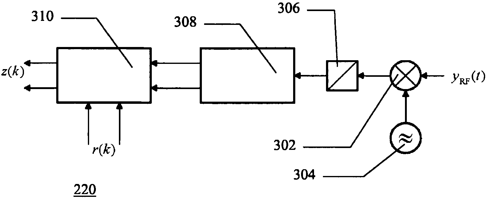
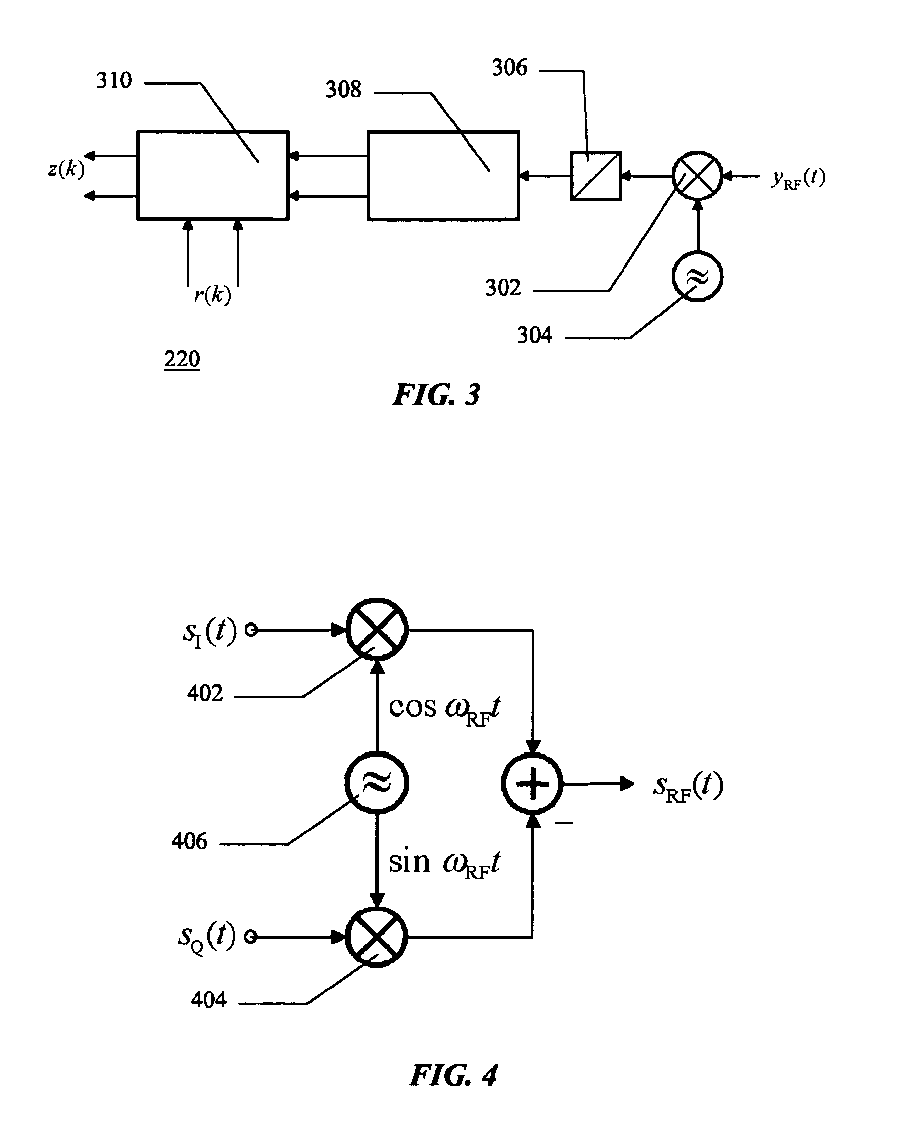
A transmitter (200) for transmitting radio signals comprising a digital signal source (102), a compensation unit (104), two digit al-to-analogue converters (106) and (108), an analogue modulator (110), an amplifier (112) an antenna (114) connected to the amplifier (112), the transmitter further comprises a front-end unit (220) connected to an estimator (230). Said front-end unit (220) comprises a mixer operably (302) connected to a local oscillator (304), an analogue-to-digital converter (306) for processing signal received from the mixer (302), a first digital filter (308) for converting signal received from the analogue-to-digital converter (306) to a baseband signal, an adaptive digital filter (310) operable to time-synchronise its output signal (z(k)) to a reference signal (r(k)) and to remove linear distortions from the signal received from the first digital filter.

Description

FIELD OF THE INVENTION[0001]The present invention relates to an apparatus and a method of transmitting radio signals, in general, and in particular to a front-end unit and a method for monitoring non-linear distortions of radio signals.BACKGROUND OF THE INVENTION[0002]A radio transmitter 100 known in the art is illustrated in FIG. 1. It comprises a digital signal source 102, which typically generates the information bearing signals in the baseband domain, (i.e. the in-phase-signal and the quadrature-signal), a compensation unit 104 for compensating the non-linear distortions, two digital-to-analogue converters (DACs) 106, 108, one for the in-phase-signal and one for the quadrature-signal, an analogue modulator 110, to modulate the baseband signal onto a radio frequency (RF) carrier, an amplifier 112 and an antenna 114.[0003]The modulation is often performed in two steps. In the first step the information bearing signal is modulated onto an intermediate-frequency (IF) carrier. The fr...

Claims


Application Information

Patent Timeline
Patent Type & Authority Patents(United States)
IPC IPC(8): H03M1/06
CPCH03F1/3247H04B1/04H04B2001/0425H04B2001/0433H03F1/3241H03F1/34H03F3/24
Inventor HAGMANNS, FRANZ-JOSEF
Owner TELEFON AB LM ERICSSON (PUBL)
Learn More