Cooling high performance computer systems

a computer system and high-performance technology, applied in the direction of electrical apparatus casings/cabinets/drawers, instruments, electrical apparatus construction details, etc., can solve the problems of insufficient simple air circulation around the electronic components that generate heat, and achieve the effect of improving the cooling of densely packed high-power electronic components

Inactive Publication Date: 2010-10-12
III HLDG 1
View PDF42 Cites 65 Cited by
  • Summary
  • Abstract
  • Description
  • Claims
  • Application Information

AI Technical Summary

Benefits of technology

[0011]It is therefore an object of the present invention to develop a comprehensive cooling architecture to provide improved cooling of densely packed high power electronic components.

Problems solved by technology

Simple air circulation around the electronic components that generate heat is often not sufficient, and methods of assisted cooling are required.

Method used


Image

  • Cooling high performance computer systems
  • Cooling high performance computer systems
  • Cooling high performance computer systems

Examples


Embodiment Construction

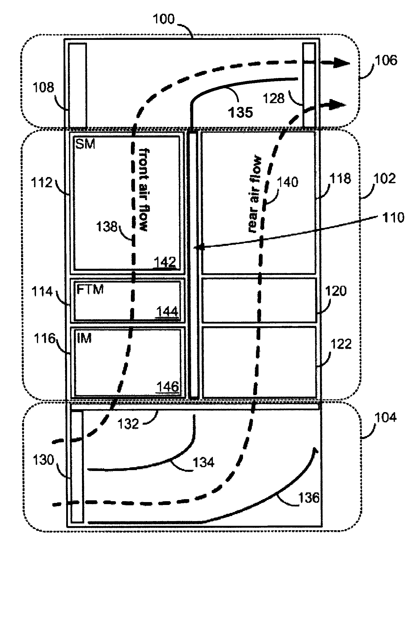
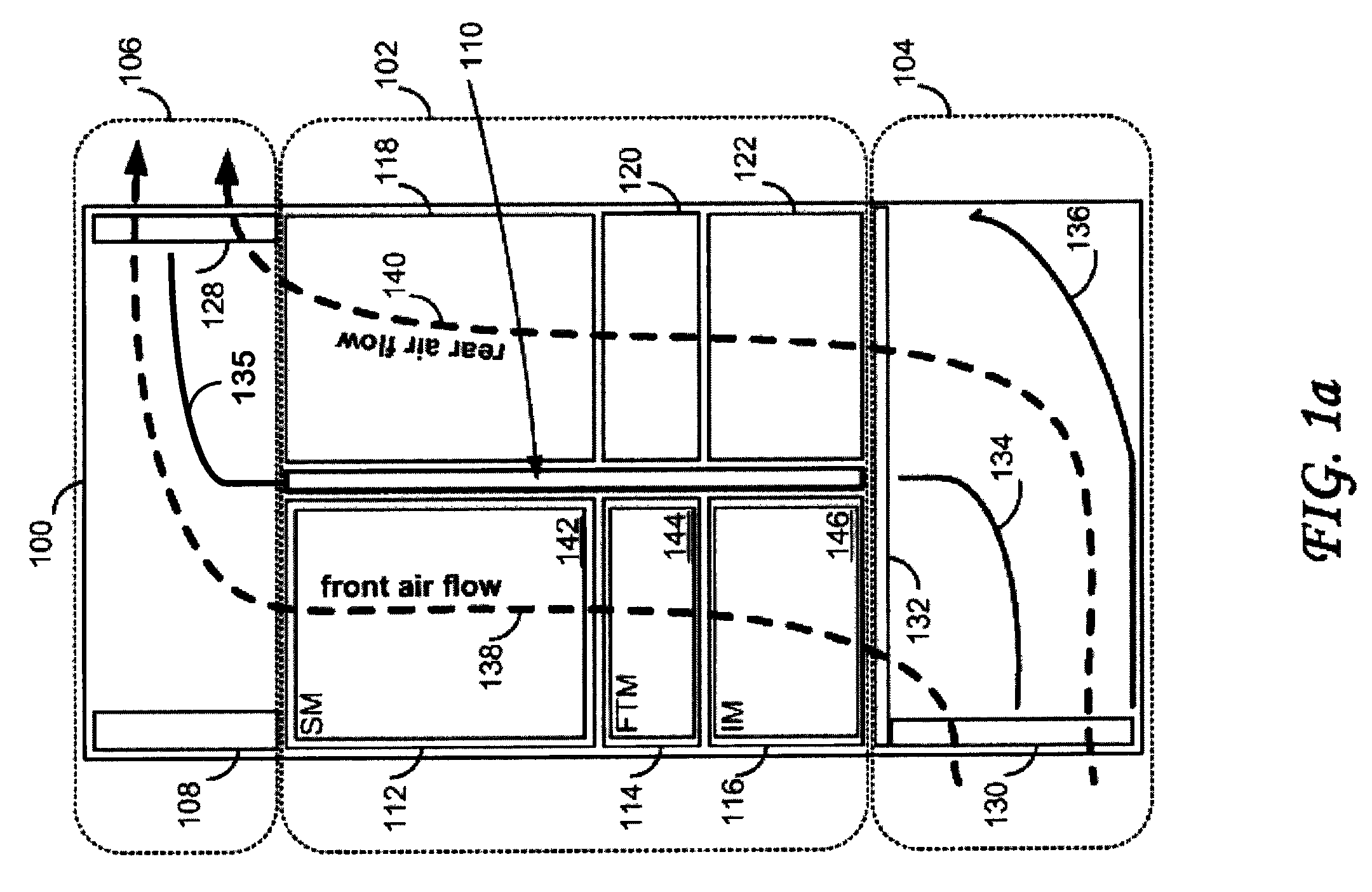
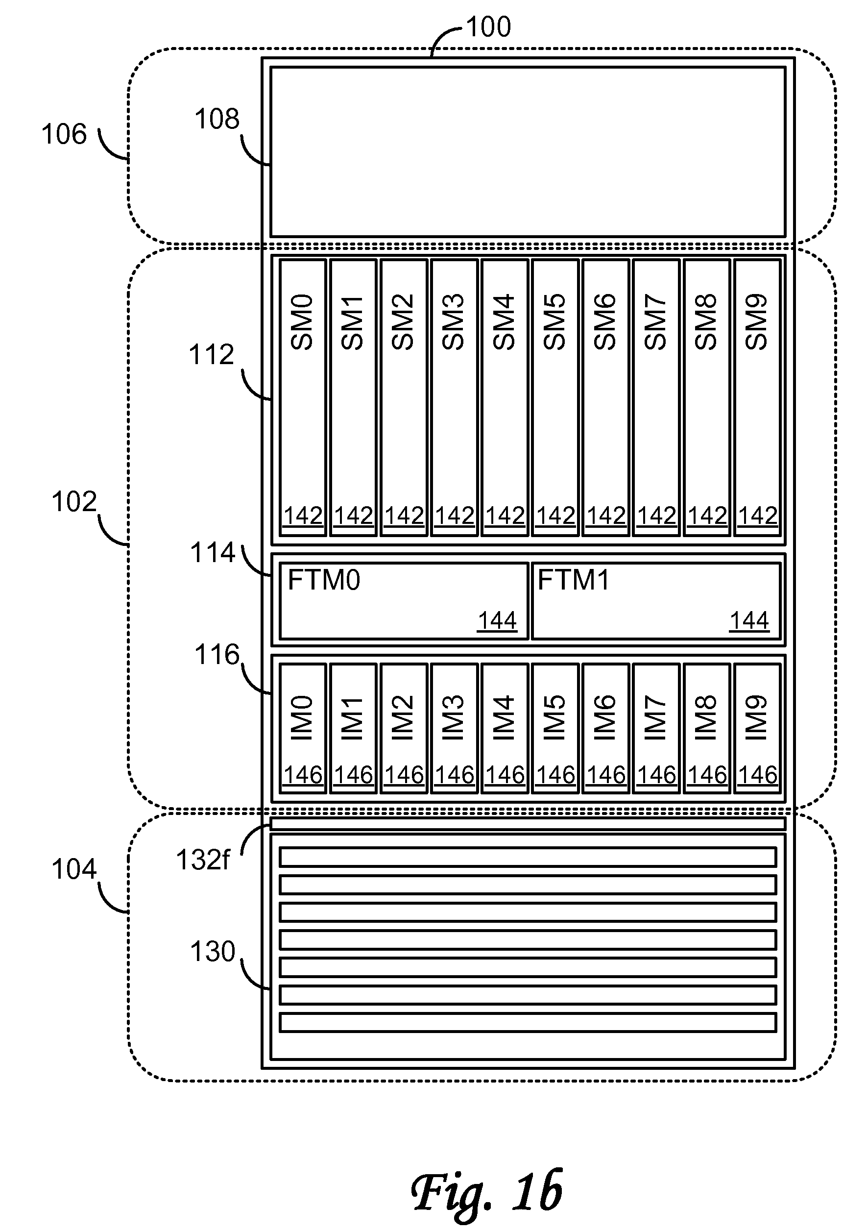
[0040]The cooling system of the present invention has been developed for high performance computer systems (such as disclosed in, for example commonly assigned and co-pending U.S. patent application Ser. No. 11 / 530,410, incorporated by reference above). Such high performance computer systems may include one or more chassis. Each chassis may include, for example:

[0041]a vertically oriented midplane, having “function” and “interconnect” slots;

[0042]up to twenty (for example) high-power “service” (or “function”) modules; and

[0043]up to twenty (for example) lower-powered “interconnect” modules.

[0044]These components are mounted (plugged in) in cages within the chassis that may also include elements of the cooling system.

[0045]FIG. 1a (cut away side view), FIG. 1b (front view), and FIG. 1c (rear view) are simplified diagrams of a chassis 100 of a high performance computer system according to an embodiment of the invention. The chassis 100 may be housed in an equipment frame or a cabinet ...


PUM


Abstract

A computer system may include a chassis defining a front and a rear. The chassis may include a vertically oriented midplane disposed therein, the midplane including a plurality of front module slots for receiving front electronic modules from the front of the chassis, and a plurality of rear module slots for receiving rear electronic modules from the rear of the chassis. A cooling system may be provided within the chassis and may generate an upwardly-directed front air flow within the chassis directed at selected ones of the front electronic modules and an upwardly-directed rear air flow within the chassis directed at selected ones of the rear electronic modules. The front air flow is separate from and independent of the rear air flow. The selected front and rear electronic modules may be disposed in the chassis so as to separate the front air flow into a plurality of substantially equal front air streams and the rear air flow into a plurality of substantially equal rear air streams, respectively.

Description

BACKGROUND OF THE INVENTION[0001]1. Field of the Invention[0002]Embodiments of the present invention relate generally to cooling systems for high performance computer systems and components thereof.[0003]2. Description of the Prior Art and Related Information[0004]The present invention relates to cooling of high performance electronic systems, and computer systems in particular, such as described in the commonly assigned and co-pending U.S. patent application Ser. No. 11 / 530,410, filed Sep. 8, 2006, entitled “Methods and Systems for Scalable Interconnect”, which application is hereby incorporated herein by reference in its entirety. Briefly, electronic components of such high performance computer systems are housed in modules that are located in one or more cages (card cages). In turn, these cages are disposed in equipment chassis or cabinets.[0005]Simple air circulation around the electronic components that generate heat is often not sufficient, and methods of assisted cooling are ...

Claims


Application Information

Patent Timeline
Patent Type & Authority Patents(United States)
IPC IPC(8): H05K7/20
CPCH05K7/20563H05K7/20736
Inventor BISSON, SYLVIOLOTZ, WILLI MANFRED
Owner III HLDG 1
Why Eureka
Try Eureka