Method for detecting objects left-behind in a scene

a technology of left-behind objects and detection methods, applied in the field of methods, can solve the problems of increasing computational costs, affecting so as to reduce processing time and improve the accuracy of the left-behind object detection method

Active Publication Date: 2010-10-12
MITSUBISHI ELECTRIC RES LAB INC
View PDF1 Cites 39 Cited by
  • Summary
  • Abstract
  • Description
  • Claims
  • Application Information

AI Technical Summary

Benefits of technology

[0014]As an advantage, the method does not require object tracking, which, eliminates the possibility of inter-frame correspondence failures, common in tracking procedures. However, the method can be integrated with tracking procedures to improve the accuracy of the left-behind object detection method.
[0015]The method does not require a model of the scene or the object. The method is primarily concerned with temporal aspects of pixel changes. Therefore, the method does not need to be trained to compensate for particular imaging conditions, such as camera angle, illumination, etc. The method can use parallelization to decrease processing time.

Problems solved by technology

However, on-line EM blends weak modes into stronger ones and distorts the model mean values.
However, the computational cost grows exponentially as the number of models in the mixture increases.
As a result, kernel, based methods are impractical for real-time applications that acquire images continuously over long time.
Even though that method aims to combine the benefits of pixel-, motion-, and region-based techniques, it has problems with periodic motion as well as non-convex objects.
However, there is a class of problems, which conventional two-class segmentation methods cannot solve.
Common sense dictates that an object left-behind in public places, such as a suitcase, backpack, or a package, can pose a significant security risk.
Unfortunately, such an object does not qualify as either background or foreground.
The main drawback of most prior art methods is the fact that in order to identify portions of the video images corresponding to an object that has been left-behind, those methods require solving a much harder problem of object tracking or object detection as an intermediate step.
Tracking objects in complex real-world scenes and in real-time is difficult.

Method used


Image

  • Method for detecting objects left-behind in a scene
  • Method for detecting objects left-behind in a scene
  • Method for detecting objects left-behind in a scene

Examples


Embodiment Construction

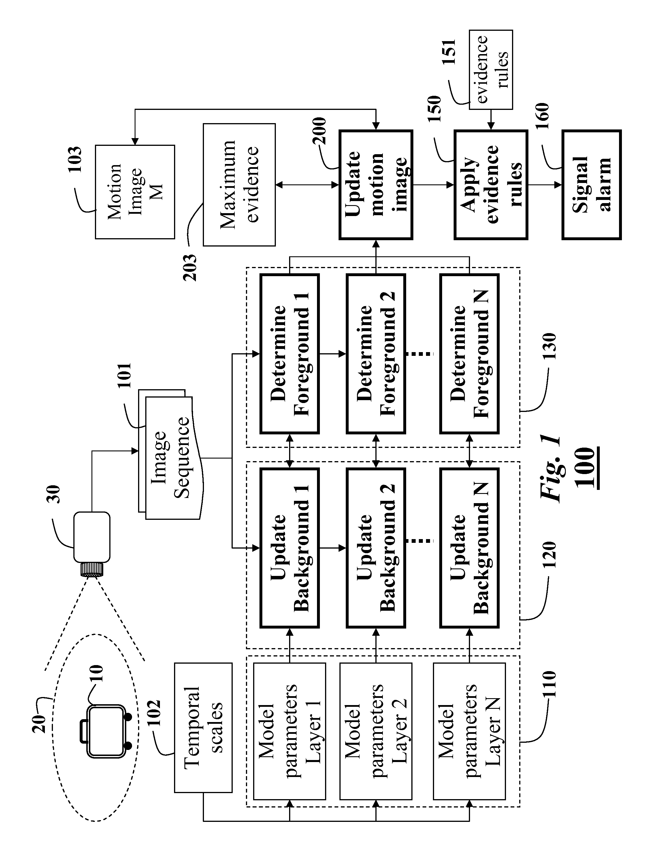
[0017]FIG. 1 is a flow diagram of a method for detecting an object left behind in a scene according to an embodiment of the invention;

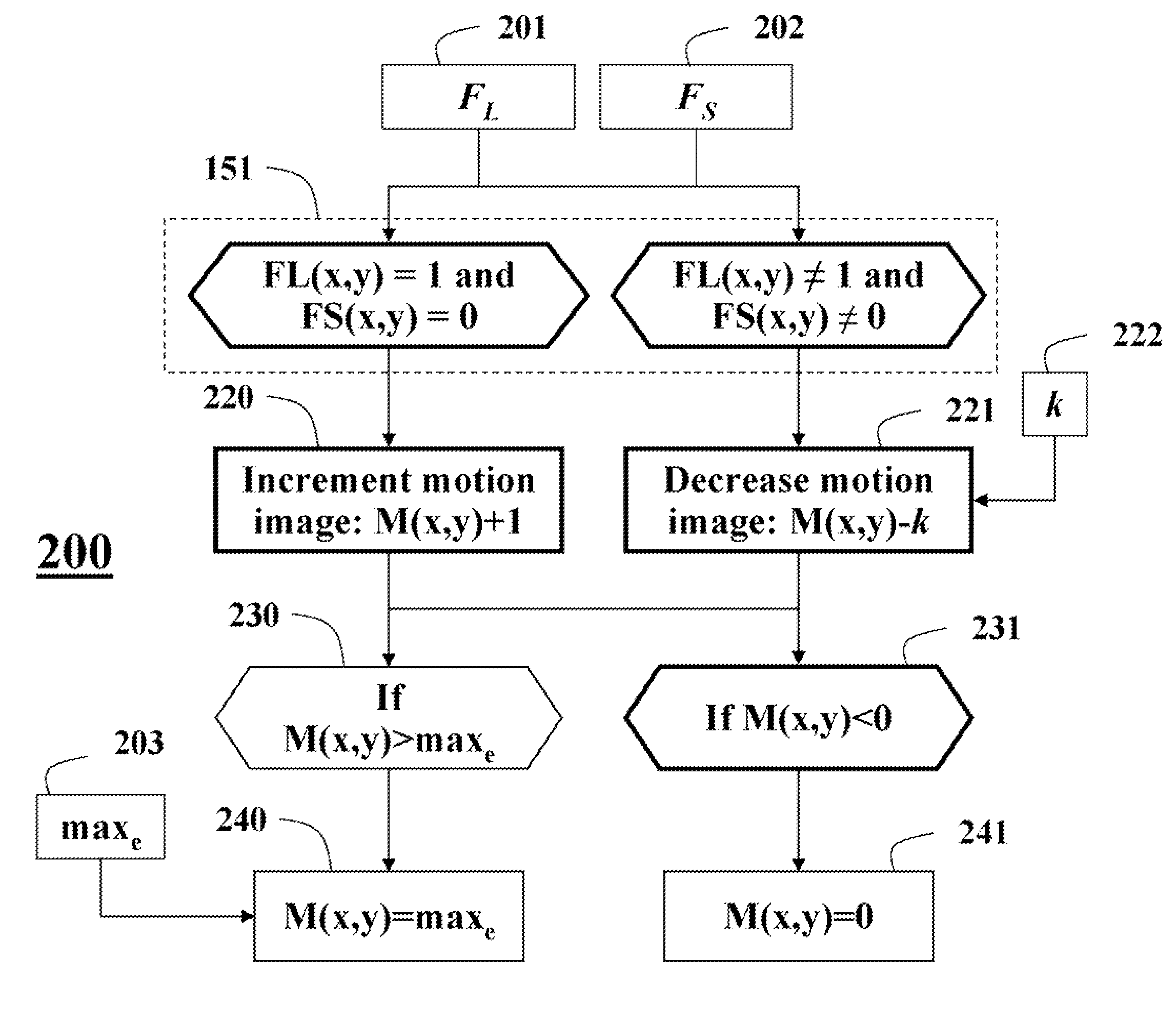
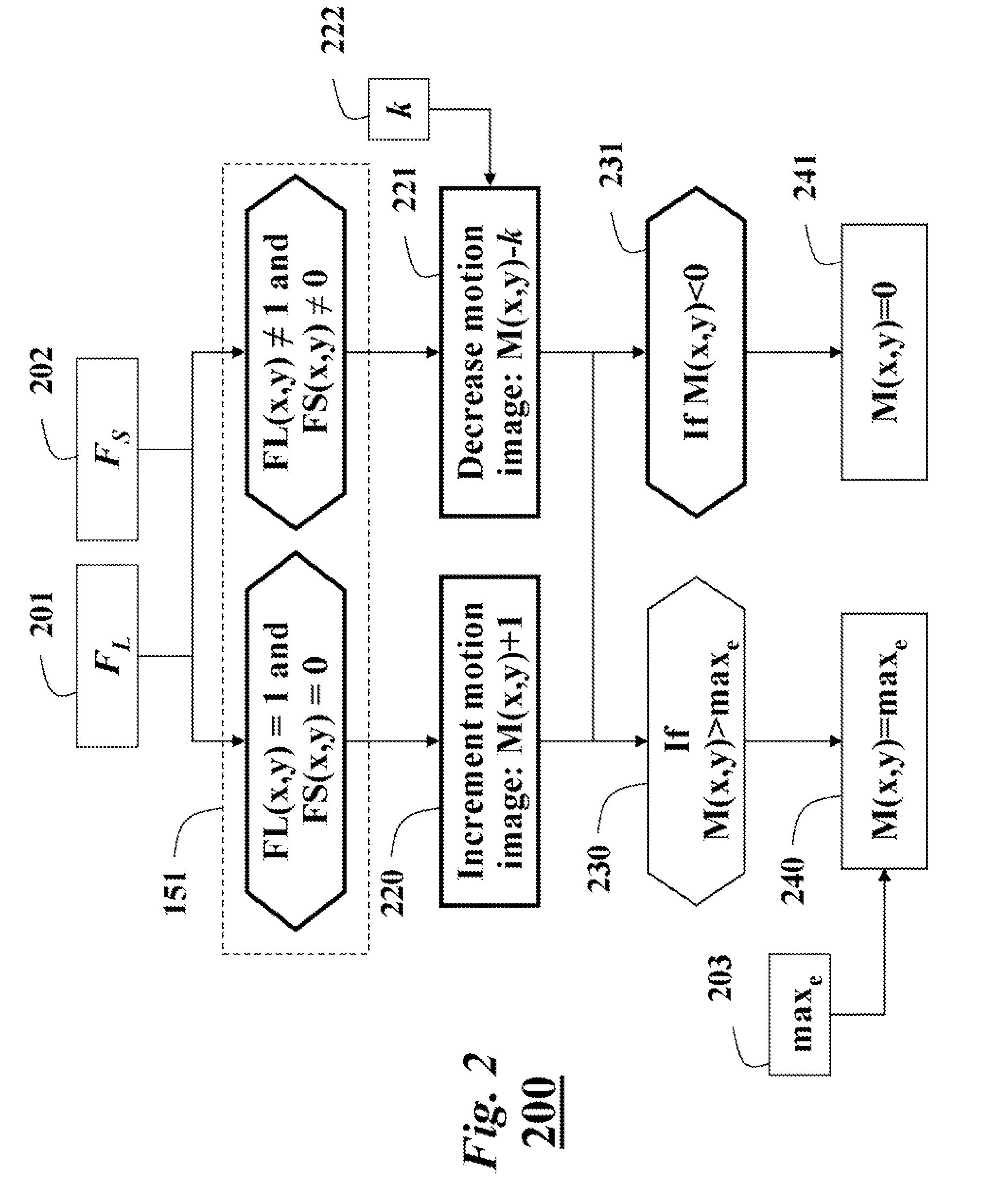
[0018]FIG. 2 is a flow diagram of a procedure for maintaining a motion image according to an embodiment of the invention; and

[0019]FIG. 3 is a block diagram, of pseudo code of a procedure for updating background model parameters according to an embodiment of the invention.

DETAILED DESCRIPTION OF THE PREFERRED EMBODIMENTS

[0020]FIG. 1 shows a method 100 for detecting an object 10 left-behind in a scene 20 according to embodiments of our invention. A camera 30 acquires a sequence of image 101 of the scene, e.g., the camera is a surveillance camera.

[0021]Our left-behind object detection method is based on an inference of pixel color evolution over time. The left-behind object can be considered as a static object in the scene, which was not there before. This observation indicates that by modeling 120 the background, which refers to long-term, static backg...


PUM


Abstract

A method detects an object left-behind in a scene by updating a set of background models using a sequence of images acquired of the scene by a camera. Each background model is updated at a different temporal scales ranging from short term to long term. A foreground mask is determined from each background model after the updating for a particular image of the sequence. A motion image is updated from the set of foreground masks. In the motion, image, each pixel has an associated evidence value. The evidence values are compared with a evidence threshold to detect and signal an object left behind in the scene.

Description

FIELD OF THE INVENTION[0001]The present invention relates generally to segmenting a sequence of images acquired of a scene by a camera into background and foreground portions, and more particularly to detecting objects that have been left-behind in the scene.BACKGROUND OF THE INVENTION[0002]In video surveillance applications, it is common to segment a sequence of images acquired of a scene by a camera into background and foreground portions so that objects in the scene can be detected and tracked. It is often assumed that the background portion is completely static, or slowly or periodically changing, while the foreground portion corresponds to groups of adjacent pixels that change much more rapidly than the pixels in the background portion.[0003]A number of background subtraction methods are known that are robust to changes in lighting, pixel noise, camera position, and the like. A simple method marks the pixels in an image whose values are different from those of an image of the s...

Claims


Application Information

Patent Timeline
Patent Type & Authority Patents(United States)
IPC IPC(8): G06K9/00
CPCG06K9/00771G06V20/52
Inventor PORIKLI, FATIH M.IVANOV, YURI A.
Owner MITSUBISHI ELECTRIC RES LAB INC
Why Eureka
Try Eureka