
Object model tree diagram

a tree diagram and object model technology, applied in the field of class diagrams, can solve the problems of laying a uml class, exacerbated these architectural challenges, and complex software system scope and scale, and achieves the effect of convenient user interaction, simple and efficient use, and convenient object model design

Active Publication Date: 2010-10-12
MICROSOFT TECH LICENSING LLC
View PDF6 Cites 30 Cited by
  • Summary
  • Abstract
  • Description
  • Claims
  • Application Information

AI Technical Summary

Benefits of technology

The invention is a system that takes a computer-readable representation of a graph of objects and creates one or more diagrams that show the relationships and properties of those objects. This approach is particularly useful for creating object models that represent domain-specific languages. The system takes advantage of the interactive capabilities of modern computer systems, such as reorganizing the diagram, searching, and using cues to make the diagrams easier to edit. The system also includes a design tool that helps create object models and an artificial intelligence component that can predict or infer actions based on probability and statistical analysis. Overall, the invention simplifies the process of creating and analyzing object models, making it easier to develop and test new concepts.

Problems solved by technology

As the complexity of software systems increase in scope and scale, companies seek techniques to manage and solve such complexities, which include recurring architectural problems, such as physical distribution, fault tolerance, replication, security, concurrency and load balancing.
Additionally, the development for the Internet, while making some communications exchanges much simpler, exacerbates these architectural challenges.
Using UML to depict class diagrams has several limitations, as follows: laying a UML class diagram out automatically is a difficult algorithmic problem which rarely gives very satisfactory results; laying a UML class diagram out manually is time-consuming, especially with respect to limiting line crossing, and in placing semantically-significant adornments so that their meaning is readily apparent; a UML diagram of a set of classes pays little regard to the fact that these classes may naturally be organized in a tree structure; and finally, there is no systematic way to expand and collapse areas of a UML diagram.
However, such conventional developmental tools such as UML, BNF, and EBNF, for example, are fraught with limitations that fail to satisfy a substantial unmet need in the art for development tools.

Method used


Image

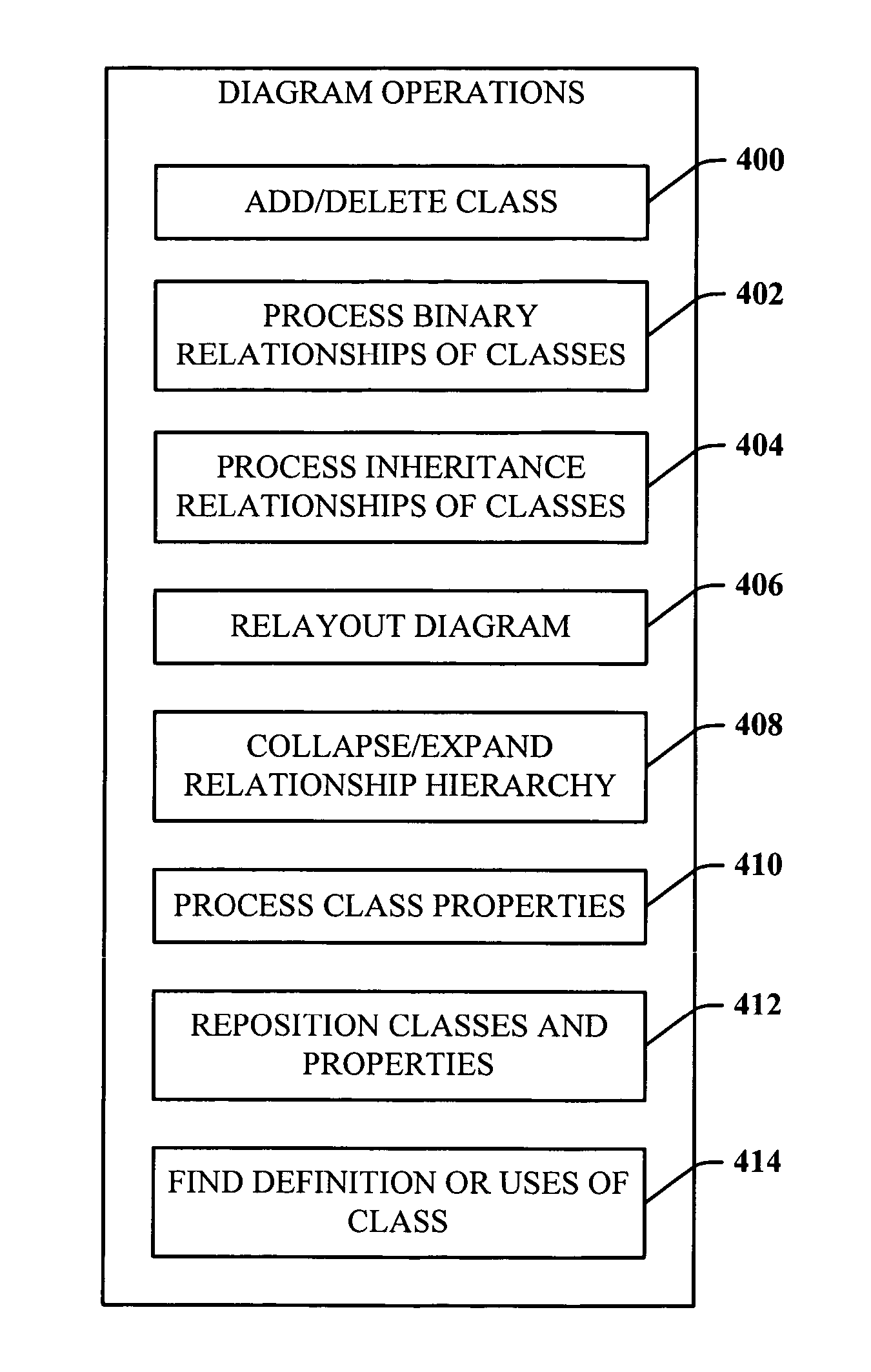
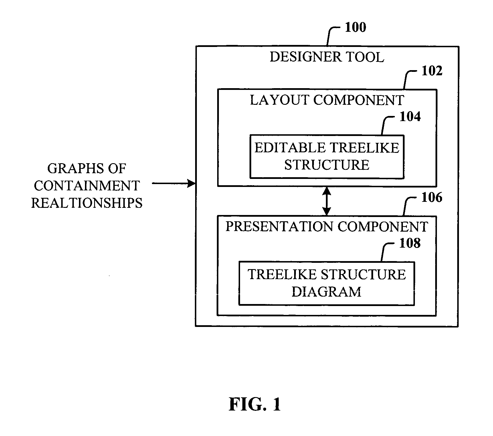
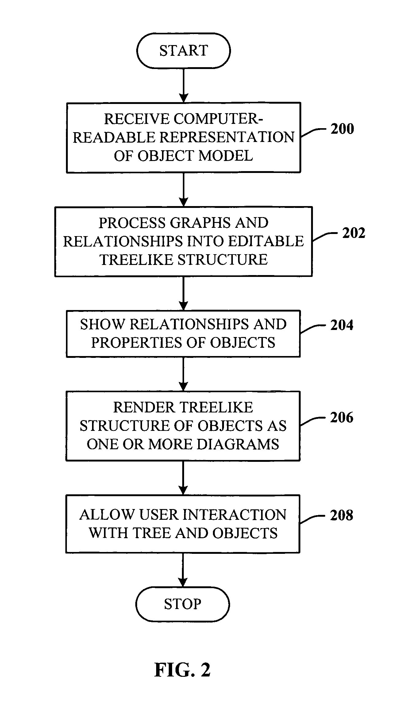
  • Object model tree diagram
  • Object model tree diagram
  • Object model tree diagram

Examples


Embodiment Construction

[0023]The invention is now described with reference to the drawings, wherein like reference numerals are used to refer to like elements throughout. In the following description, for purposes of explanation, numerous specific details are set forth in order to provide a thorough understanding of the subject invention. It may be evident, however, that the invention can be practiced without these specific details. In other instances, well-known structures and devices are shown in block diagram form in order to facilitate describing the invention.

[0024]As used in this application, the terms “component” and “system” are intended to refer to a computer-related entity, either hardware, a combination of hardware and software, software, or software in execution. For example, a component can be, but is not limited to being, a process running on a processor, a processor, an object, an executable, a thread of execution, a program, and / or a computer. By way of illustration, both an application ru...


PUM


Abstract

A designer tool that facilitates design of an object model. The tool takes as input a computer-readable representation of a graph of objects (e.g., classes), and creates automatically one or more diagrams that depict these classes as editable trees showing their relationships and properties. These graphs naturally have a tree-like structure which is exploited by the approach. The design tool system includes a layout component that receives as input one or more of the graphs, and converts the one or more graphs into the editable treelike structure. The system further comprises a presentation component that presents the editable treelike structure as a treelike structure diagram, and facilitates user interaction therewith. The tool can be used for opening, editing and saving existing object model files or to create new ones.

Description

TECHNICAL FIELD[0001]This invention is related to the presentation of diagrams, and more specifically, to the presentation of class diagrams in software-related tools.BACKGROUND OF THE INVENTION[0002]As the strategic value of software increases for many companies, software vendors continually seek out new techniques to automate the production of software and to improve quality and reduce cost and time-to-market. These techniques include component technology, visual programming, patterns and frameworks. As the complexity of software systems increase in scope and scale, companies seek techniques to manage and solve such complexities, which include recurring architectural problems, such as physical distribution, fault tolerance, replication, security, concurrency and load balancing. Additionally, the development for the Internet, while making some communications exchanges much simpler, exacerbates these architectural challenges.[0003]One conventional technique called the Unified Modeli...

Claims


Application Information

Patent Timeline
Patent Type & Authority Patents(United States)
IPC IPC(8): G06F3/048G06F9/44
CPCG06F8/10G06F8/34
Inventor COOK, STEPHEN JOHNJONES, GARETH ALUNKENT, STUART JOHN HARDINGWILLS, ALAN CAMERON
Owner MICROSOFT TECH LICENSING LLC
Learn More