Vehicle lamp housing with transparent cover welded thereon, and method

a technology of transparent cover and vehicle lamp, which is applied in the field of vehicle lamps, can solve the problems of deteriorating appearance, inability to meet the recent needs of three-dimensional design, and relatively small light irradiation area

Inactive Publication Date: 2010-10-19
KOITO MFG CO LTD
View PDF17 Cites 7 Cited by
  • Summary
  • Abstract
  • Description
  • Claims
  • Application Information

AI Technical Summary

Benefits of technology

[0015]According to the above aspects of the invention, the inclination angle of the welding face portion of the transparent cover with respect to the pressing direction is closer to a right angle than the inclination angle of the front face of the transparent cover with respect to the pressing direction. Thus, the pressing force reliably acts between the transparent cover and the housing in spite of the degree of the curvature of the front face of the transparent cover, whereby the welding face portion of the transparent cover can be closely contacted to the housing. Namely, a transmission of the pressing force can be ensured to place the welding face portion of the transparent cover into contact with the housing is transmitted.
[0006]When attaching the transparent cover and the housing, the related art generally employs a method in which a seal leg is protrusively provided at a peripheral edge portion of the transparent cover while a groove for receiving the seal leg is formed on the housing. The seal leg of the transparent cover is received by the groove of the housing via a sealing material or an adhesive. According to this attaching method, the seal leg and the groove are provided so as to protrude outwardly from the peripheral edge portions of the transparent cover and the housing. Thus, when seeing the transparent cover from a front side, there appears a portion having a relatively large area where light does not pass through (that is, a dark portion) at the peripheral edge portion of the transparent cover. Therefore, there has been a problem that a light irradiation area is relatively small as compared with the entire size.
[0040]The maximum thickness Tmax (see FIG. 6) of a portion of the transparent cover 3 where the welding face portion 31 is formed is preferably 4.5 mm or less in order to prevent a molding sink from being generated due to an excessive change of the thickness at the time of the molding. Thus, deterioration of an appearance of the front face (a design surface) 32 of the transparent cover 3 can be avoided. Further, because the molding sink is prevented from being generated, diffused refraction of the welding light ray, such as a laser, can be prevented, thereby reducing the possibility of welding failures.

Problems solved by technology

Therefore, there has been a problem that a light irradiation area is relatively small as compared with the entire size.
However, there is a problem that excessive molten materials stick out from the joining portion, thereby deteriorating an appearance when the stuck out portion is seen from the front side via the transparent cover.
Further, because configurations to which the above methods can be applied is limited (e.g., an inclination angle is limited; it is required to be substantially flat in a vibration direction in the vibration welding, and it cannot be steeply inclined with respect to a pressing direction of a hot plate in the hot plate welding), these methods cannot cope with the recent needs of a three-dimensional design.
However, according to a light welding, such as the laser welding, a defective joining occurs when a welding portion of the transparent cover and a welding portion of the housing are not reliably in contact with each other.
Nevertheless, because the transparent cover and the housing of a vehicle lamp are resin molded parts, it is difficult to obtain a shape in conformity with the actual design due to an influence of a warpage or a flexure after the molding.
Thus, it is difficult to surely make the transparent cover contact with the housing along the entire periphery thereof.
When the transparent cover is not surely made in contact with the housing, the heat applied to the housing by the irradiation of a light ray, such as laser light, cannot be transmitted the transparent cover and, thus, the welding cannot be performed.

Method used


Image

  • Vehicle lamp housing with transparent cover welded thereon, and method
  • Vehicle lamp housing with transparent cover welded thereon, and method
  • Vehicle lamp housing with transparent cover welded thereon, and method

Examples


Embodiment Construction

[0026]Hereinafter, a vehicle lamp and a method of manufacturing the vehicle lamp according to exemplary embodiments of the invention will be explained with reference to the drawings.

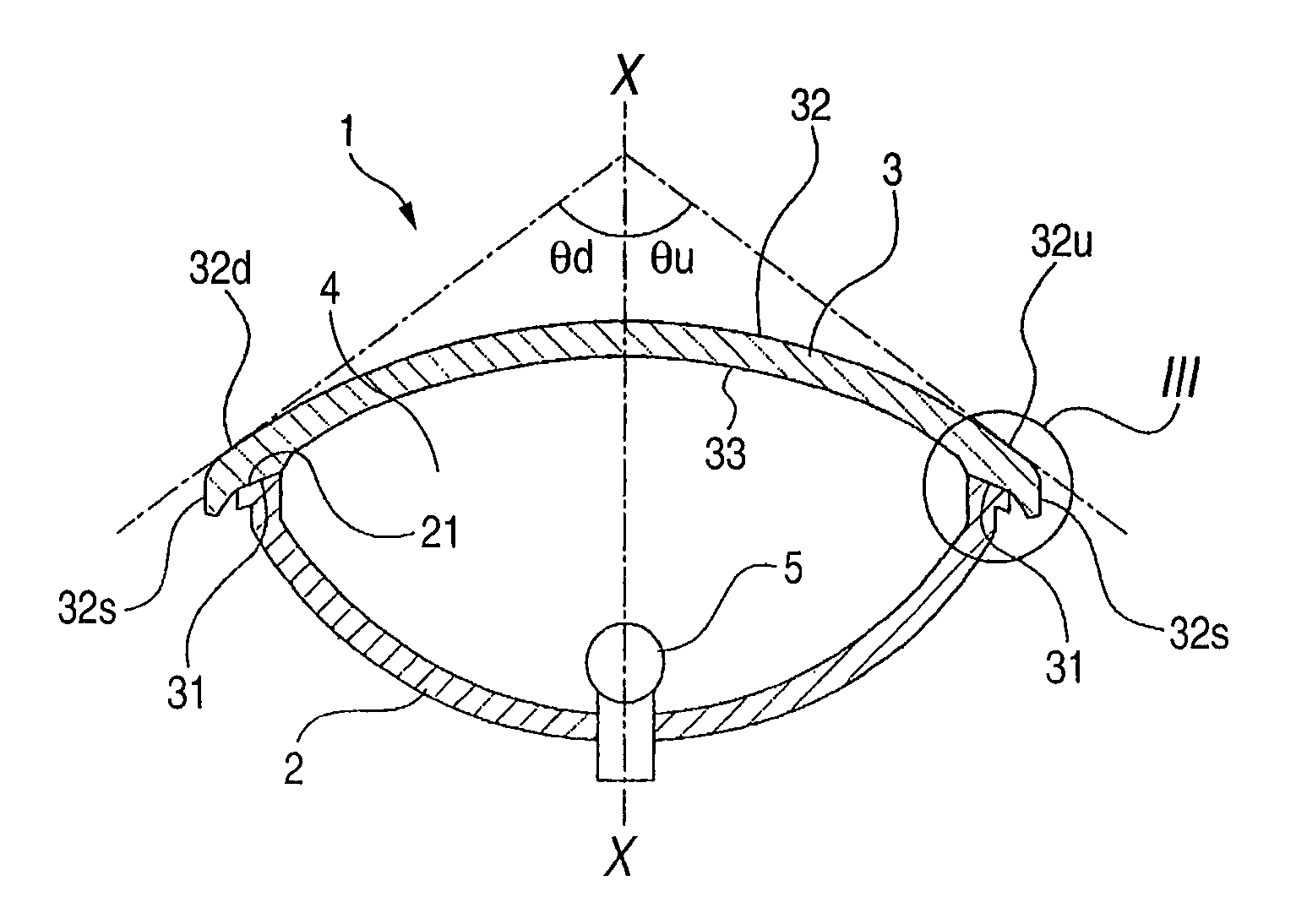
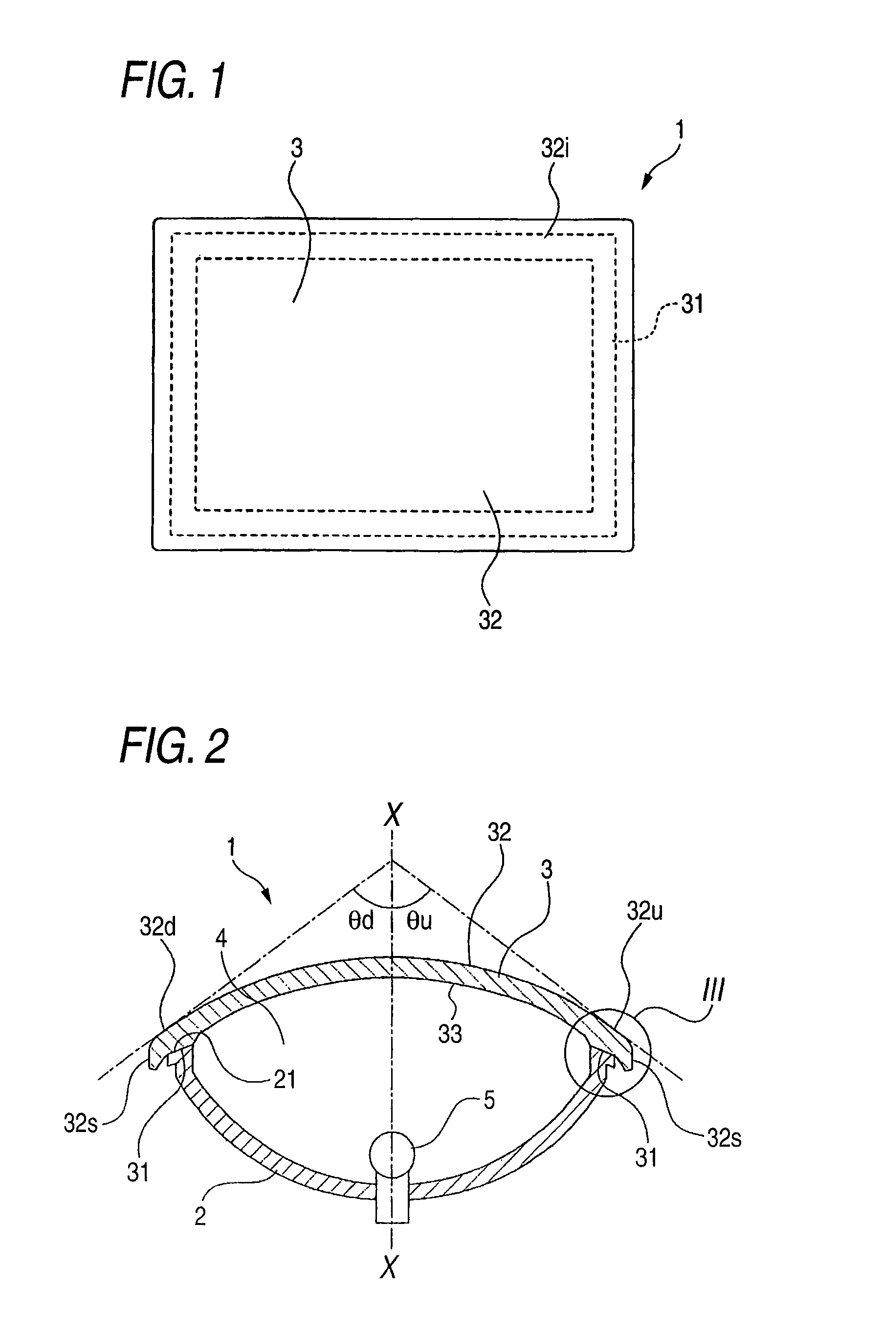
[0027]FIG. 1 shows a schematic front view of a vehicle lamp according to an exemplary embodiment of the invention, and FIG. 2 shows a schematic longitudinal sectional view of the vehicle lamp.

[0028]The lamp 1 is configured such that an opening on a front face of a housing 2 is covered by a transparent cover 3, and a light source 5 is disposed inside a lamp chamber 4 defined by the housing 2 and the transparent cover 3.

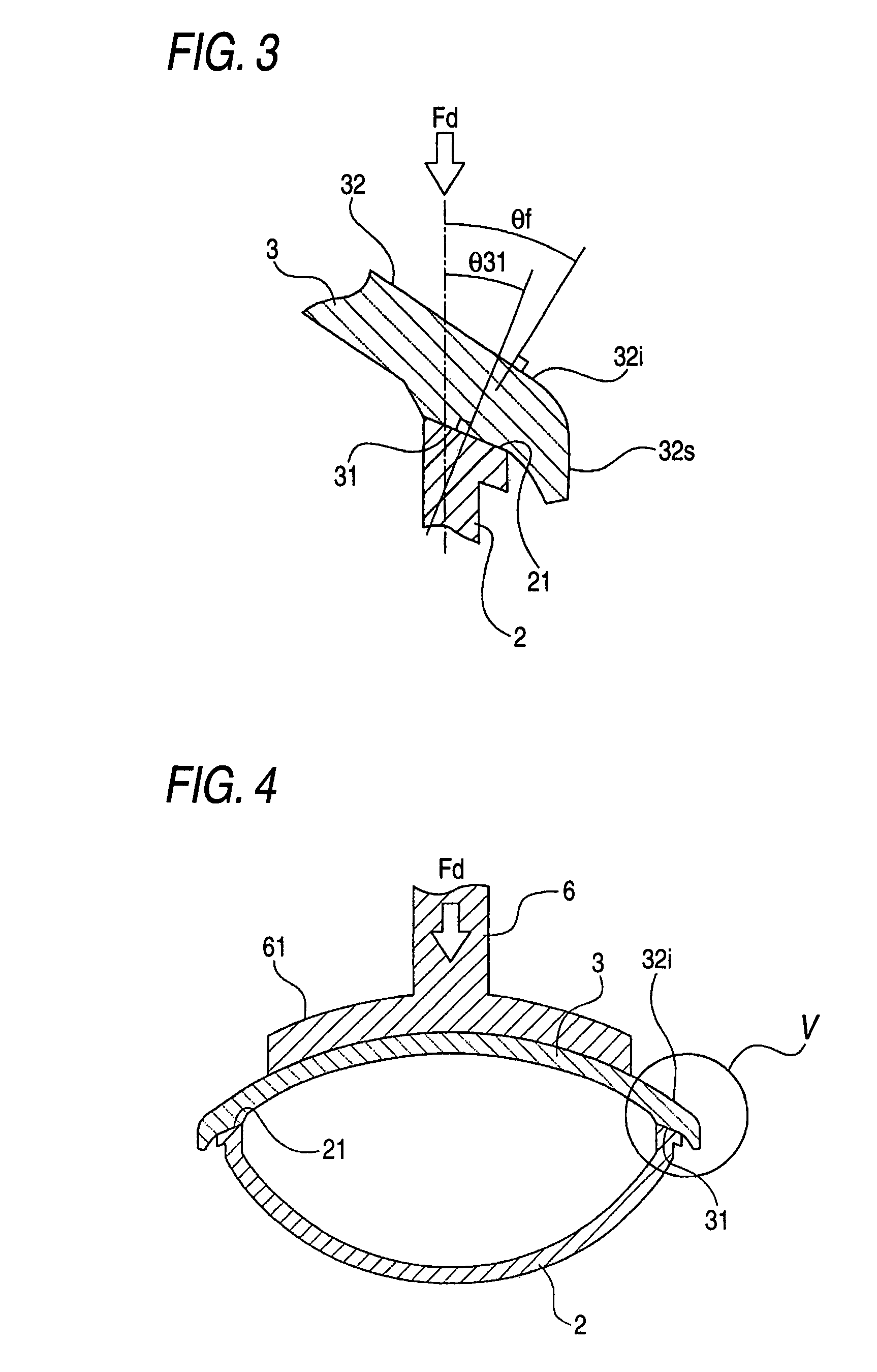
[0029]A welding face portion 31 is formed along the entire circumferential portion of the rear face of the transparent cover 3, and the welding face portion 31 is joined to a welding face portion 21 formed along a peripheral edge portion of the opening on the front face of the housing 2 by light ray welding. More specifically, a welding light ray, which is a coherent / incoherent electromagne...


PUM

PropertyMeasurementUnit
thicknessaaaaaaaaaa
transparentaaaaaaaaaa
angleaaaaaaaaaa

Abstract

A method of manufacturing a vehicle lamp includes providing a housing having a front opening and a transparent cover having a curved front face and a rear face having a welding face portion. The welding face portion of the transparent cover is placed in a closely contacting state with respect to the housing and the transparent cover is joined with the housing so as to close the front opening of the housing by irradiating a welding light ray toward the welding face portion through the transparent cover. The placing includes applying a pressing force against the housing to the transparent cover in a predetermined direction such that an angle of the welding face portion of the transparent cover with respect to the predetermined direction is closer to a right angle than an angle of the front face of the transparent cover corresponding to the welding surface with respect to the predetermined direction.

Description

CROSS-REFERENCE TO RELATED APPLICATIONS[0001]The present invention claims priority from Japanese Patent Application No. 2006-175336 filed on Jun. 26, 2006, the entire content of which is incorporated herein by reference.BACKGROUND OF INVENTION[0002]1. Field of the Invention[0003]The present invention relates to a vehicle lamp and a method of manufacturing the vehicle lamp. More specifically, the present invention relates to a technique of reliably joining a housing, inside of which a light source, etc. is housed, and a transparent cover, which closes a front opening of the housing.[0004]2. Background Art[0005]In a method of manufacturing a vehicle lamp such as a lamp for an automobile, it is necessary to attach a transparent cover, generally called as a lens, to a housing so as to cover a front opening thereof.[0006]When attaching the transparent cover and the housing, the related art generally employs a method in which a seal leg is protrusively provided at a peripheral edge portio...

Claims


Application Information

Patent Timeline
Patent Type & Authority Patents(United States)
IPC IPC(8): F21V15/01B29C65/14G02B7/00F21W107/10
CPCB29C65/1635B29C66/301F21S48/255B29C66/81423B29C66/542B29C66/8322B29C66/131B29C66/24244B29C65/1606B29C66/7392B29K2033/12B29L2031/747B29C65/1612B29L2031/30B29K2995/0027B29C66/73365B29C66/71B29C66/723F21S43/51B60Q1/02F21V3/00
Inventor YAMAZAKI, KAZUHIROSUZUKI, MICHIHIKOYASUDA, RYOSUKEOTANI, HARUO
Owner KOITO MFG CO LTD
Why Eureka
Try Eureka