Joining element and method for its attachment on a surface

a technology of joining elements and surfaces, applied in the field of joining elements, can solve problems such as temporary deformation of flange-like extension

Active Publication Date: 2010-10-19
BOLLHOFF VERBINDUNGSTECHNIK GMBH +1
View PDF44 Cites 24 Cited by
  • Summary
  • Abstract
  • Description
  • Claims
  • Application Information

AI Technical Summary

Benefits of technology

[0006]The joining element comprises a sleeve-shaped accommodation part, which exhibits in its interior a component of a positive and / or non-positive connection to be produced with an element to be attached, in particular a thread or a snap-on element, a flange-like extension connecting to the accommodation part with an indentation on the side turned away from the accommodation part and fillets on the side turned toward the accommodation part, which are designed in such a way that the joining element can be attached to the surface by filling the indentation with a suitable means of attachment and stiffness cracks in the flange-like extension can be reduced.
[0007]The above joining element exhibits an inverted T-shaped form, in which the broader piece serves the purpose of attachment of the joining element on the surface. The broader piece, which provides a sufficient seat opposite the surface of a component, is combined with a sleeve-shaped accommodation part. The sleeve-shaped accommodation part is preferably constructed like a hollow cylinder, so that the interior of the hollow cylinder, in particular the inner surface, can be used for the production of a desired connection with an additional component. This desired connection is for example a positive or non-positive connection or a combined positive and non-positive connection. The broader piece of the T-shaped joining element in addition exhibits an indentation for the support of the connection to the surface of a component, which can be filled with a means of attachment, for example adhesive. The flange-like extension of the joining element is placed on the surface for attachment and is therefore exposed to loading. This loading results in temporary deformations of the flange-like extension, whose mechanical stresses load the joining element. In order to limit this loading of the joining element so that a destruction of the joining element during placement on the surface is prevented, the flange-like extension exhibits fillets on the side turned toward the accommodation part. These fillets prevent stiffness cracks in the accommodation part so that in this way mechanical stress concentrations are reduced or even prevented.

Problems solved by technology

This loading results in temporary deformations of the flange-like extension, whose mechanical stresses load the joining element.

Method used


Image

  • Joining element and method for its attachment on a surface
  • Joining element and method for its attachment on a surface
  • Joining element and method for its attachment on a surface

Examples


Embodiment Construction

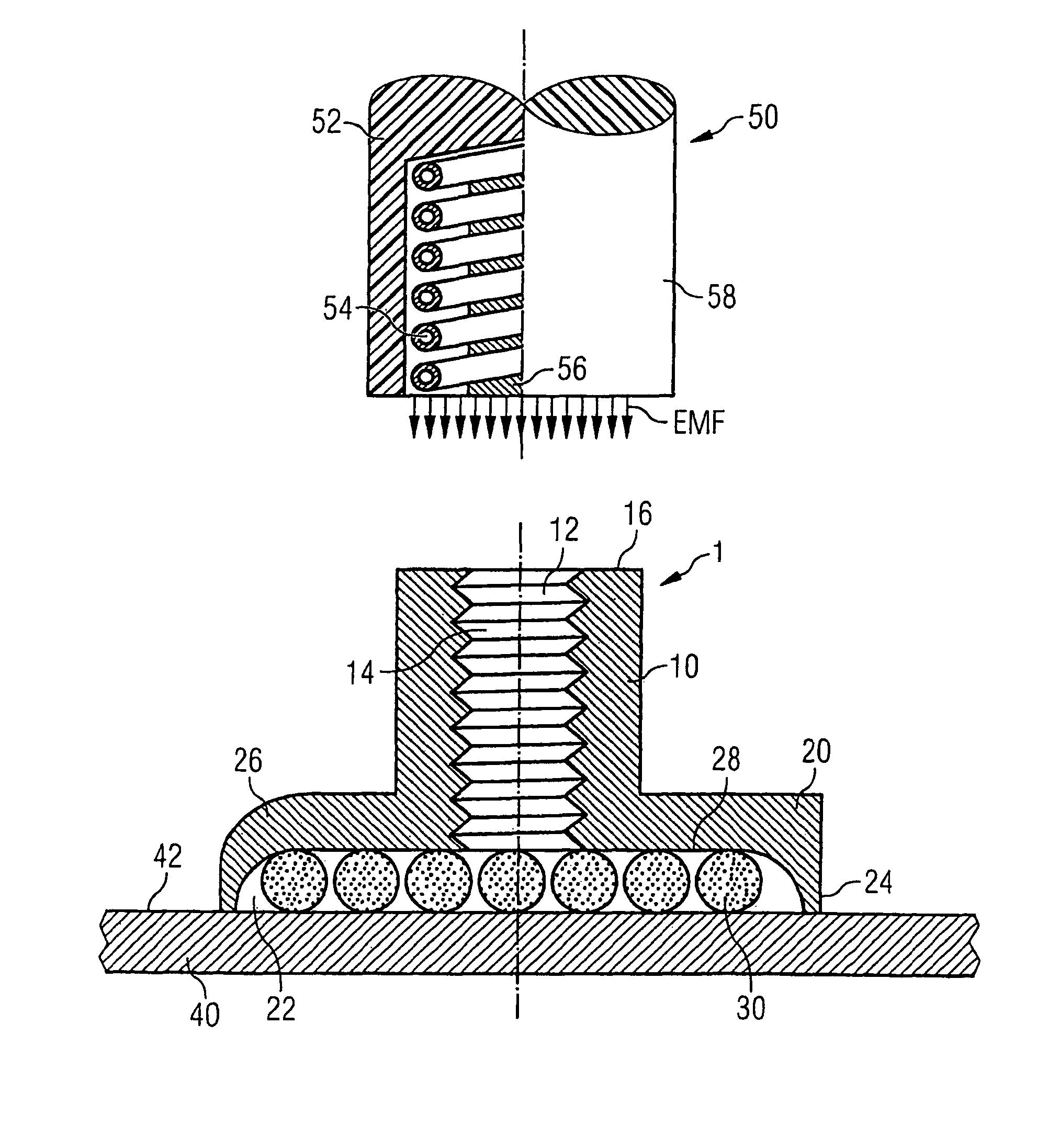
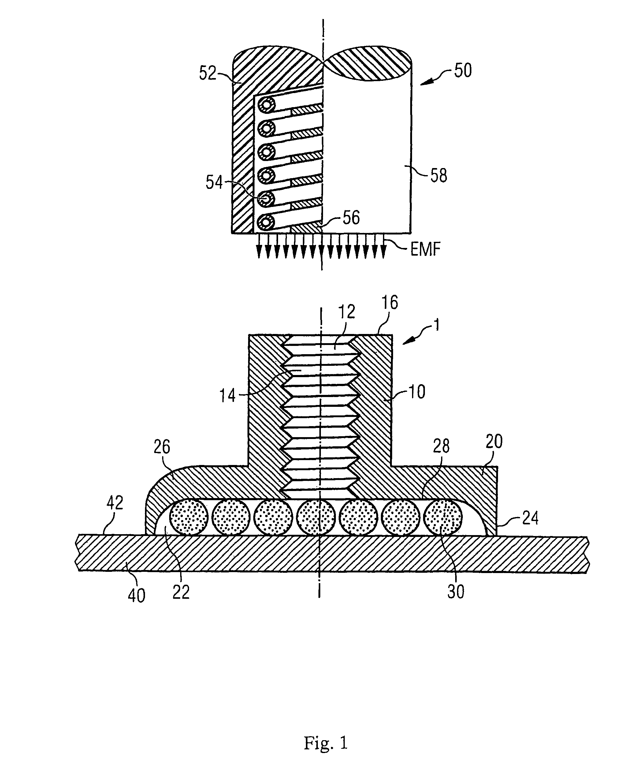
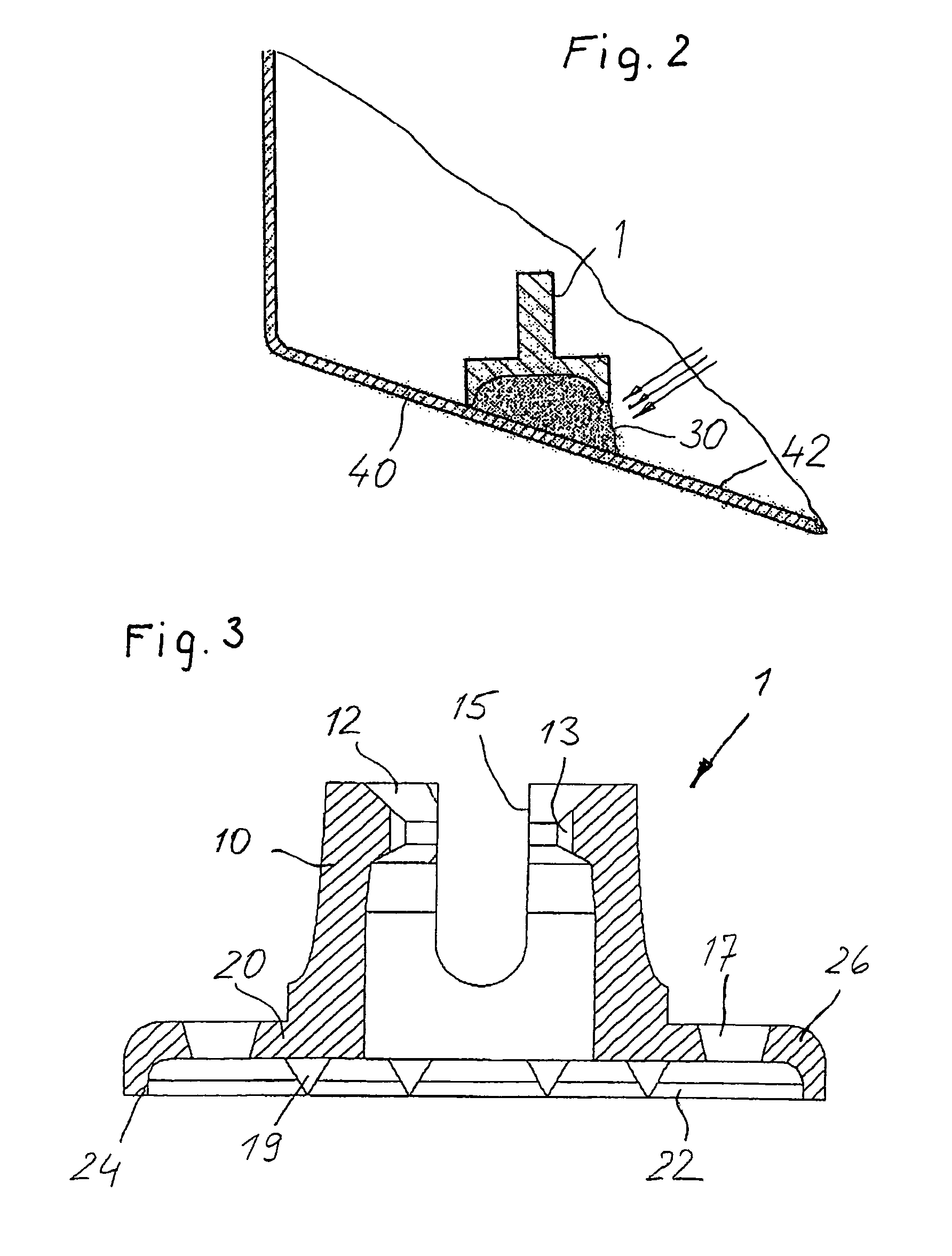
[0021]The accompanying FIG. 1 shows as an example a thin-walled component 40, to which the joining element 1 is attached. In accordance with different fields of application the component 40 is made of sheet metal, plastic or glass and is used among other things in mobile telephones, computers, motor vehicles and the like. In spite of the attachment of the joining element 1 on the surface 42 of the component 40 the outward appearance of the component 40 is not disturbed. The joining element 1 is namely connected to the component 40 in such a way that no openings, boreholes, material accumulations, dents, sink marks, color changes in the material, marks or the like occur or are necessary.

[0022]As one can see with the help of FIG. 1, the attachment element 1 has an inverted T-shaped form which is formed by a sleeve-shaped accommodation part 10 and by a flange-like extension 20. The accommodation part 10 and the extension 20 are integrally connected to each other or are connected in ano...


PUM

PropertyMeasurementUnit
stress concentrationsaaaaaaaaaa
timeaaaaaaaaaa
temperatureaaaaaaaaaa

Abstract

A joining element and a method for attaching the joining element on a surface of a component are disclosed. The joining element comprises a sleeve-shaped accommodation part for the accommodation of an element to be attached in the interior of the accommodation part. A flange-type extension having an indentation is provided wherein said indentation can be filled with suitable means of attachment for mounting the joining element onto surface.

Description

FIELD OF THE INVENTION[0001]The present invention relates to a joining element and a method for its attachment on a surface.BACKGROUND OF THE INVENTION[0002]Various applications, for example in the field of computers, mobile communications technology or in automobile manufacture require joining elements which permanently or detachably connect different parts to each other. Known joining elements frequently penetrate the components or are fused into their surfaces. However, this results in an unattractive appearance of the component surface.[0003]It is additionally a disadvantage when rear markings, sink marks or dents are necessary for the connection of components. In this connection it is also not acceptable when for example the attachment of joining elements results in color changes of the component material.[0004]Therefore it is the object of the present invention to provide a joining element and a method for its attachment on a component surface with which simultaneously a relia...

Claims


Application Information

Patent Timeline
Patent Type & Authority Patents(United States)
IPC IPC(8): B32B9/00
CPCB29C65/1435B29C65/46B29C66/80B29C66/919B62D27/026F16B11/006F16B21/073F16B37/048B29C65/1483B29C65/3612B29C66/91651B29C66/9141B29C66/91645B29C66/474B29C65/48B29C65/1406B29C66/7392B29C65/4835B29C65/4845B29C66/116B29C66/30221B29C66/4344B29C66/949B29C2035/0827B29K2033/12B29K2069/00B29K2101/10B29K2995/0026B29C65/1409Y10T428/14Y10T428/1438Y10T428/24339B29C66/91653B29C66/91655Y10T403/7039Y10T403/47B29C65/00B29C66/73365B29C66/71B29C66/1122F16B2200/10
Inventor STUMPF, MICHAELMESCHUT, GERSONDRAHT, TORSTENWEIGEL, GUDRUNWALTHER, CHRISTIAN
Owner BOLLHOFF VERBINDUNGSTECHNIK GMBH
Why Eureka
Try Eureka