Method of charging rechargeable battery and protection circuit for rechargeable battery

a rechargeable battery and protection circuit technology, applied in safety/protection circuits, electric vehicles, transportation and packaging, etc., can solve the problems of increasing the cost of protection circuit boards and the manufacturing cost of rechargeable batteries, and causing ignition or explosion

Inactive Publication Date: 2010-10-19
SAMSUNG SDI CO LTD
View PDF18 Cites 4 Cited by
  • Summary
  • Abstract
  • Description
  • Claims
  • Application Information

AI Technical Summary

Benefits of technology

[0014]It is therefore an object of the present invention to provide an improved method for charging a rechargeable battery and an improved protection circuit for the rechargeable battery.
[0016]To achieve these and other objects, the method for charging the rechargeable battery according to the principles of the present invention includes perceiving whether the battery is charged or not by the protection circuit which senses the voltage of a bare cell, maintaining a low charging rate by the protection circuit which changes a direct voltage applied between a gate electrode and a source electrode of a charging FET, and controlling the amount of the current flowing from the source electrode to a drain electrode of the charging FET at a low level. The charging FET is installed in series between one terminal of the bare cell and one terminal of the charger.

Problems solved by technology

Because energy is stored in batteries, if problems such as an internal short circuit occurs, ignition or explosion may occur as the stored energy is released in a short period of time.
In the contemporary protection circuit, however, costs of the posister and the pre-charging FET of the bypass circuit are high, thereby increasing the cost of a protection circuit board and the manufacturing cost of the rechargeable battery.

Method used


Image

  • Method of charging rechargeable battery and protection circuit for rechargeable battery
  • Method of charging rechargeable battery and protection circuit for rechargeable battery
  • Method of charging rechargeable battery and protection circuit for rechargeable battery

Examples


first embodiment

[0057]FIG. 4 illustrates a flow chart of charging process of the rechargeable battery according to the principles of the present invention. The charging process of the rechargeable battery may include a step of detecting charge (S10) and a step of maintaining a low charging rate (S20).

[0058]In the step of detecting charge (S10), protection circuit 200 detects whether the initial charge is obtained or not by sensing the terminal voltage of bare cell 10. The method for sensing the terminal voltage of bare cell 10 may be performed by measuring the terminal voltage of bare cell 10 by a voltage comparator (not shown) built in protection circuit 200. Alternatively, it is possible to detect whether the initial charge is obtained or not by sensing the impedance of bare cell 10.

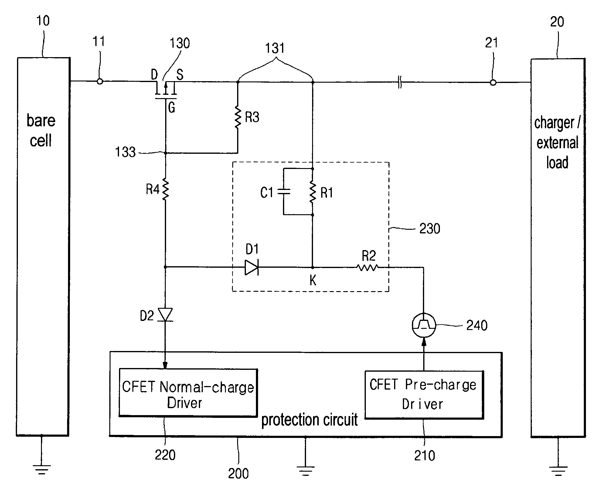
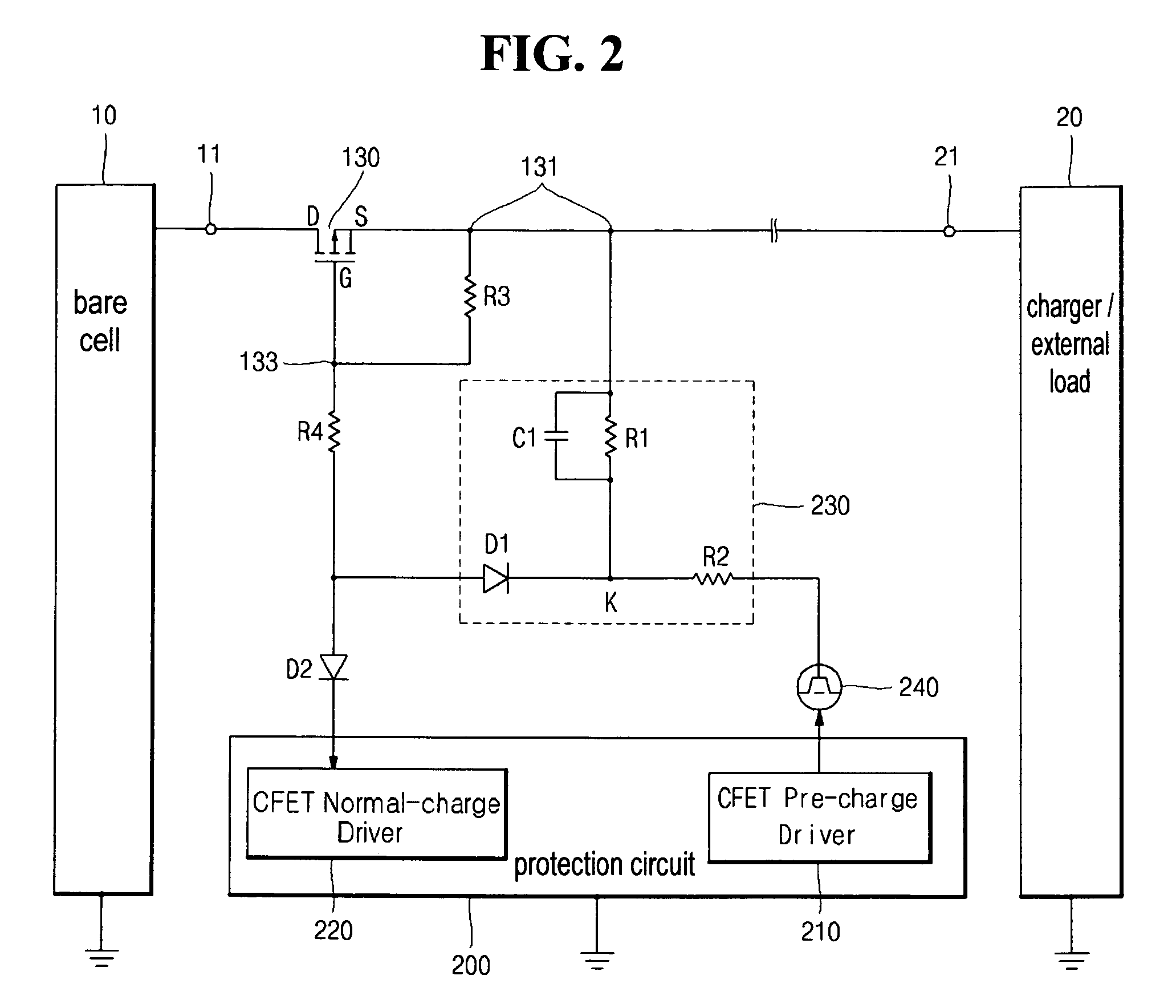
[0059]In the step of maintaining a low charging rate (S20), protection circuit 200 controls the amount of the current flowing from source electrode S to drain electrode D of charging FET 130 to be at a low level by ad...

second embodiment

[0066]Alternatively, in the present invention, following the step of maintaining a low charging rate (S20), a step of perceiving passage of time (S130) and a step of maintaining a high charging rate (S140) may be performed as illustrated in FIG. 5.

[0067]In the step of perceiving passage of time (S130), protection circuit 200 perceives the passage of a certain time after bare cell 10 is charged by the initial pre-charge charging.

[0068]The step of maintaining a high charging rate (S140) is performed after the step of perceiving passage of time (S130). In the step of maintaining a high charging rate (S140), protection circuit 200 makes the amount of the current flowing through charging FET 130 more than the amount of the current flowing through charging FET 130 in the step of maintaining a low charging rate (S20), by applying relatively high direct voltage, which is higher than the direct voltage in the step of maintaining a low charging rate, to source electrode S of charging FET 130....

third embodiment

[0070]Alternatively, in the present invention, following the step of maintaining a low charging rate (S20), a step of perceiving passage of time (S230) and a step of normal charge (S240) may be performed as illustrated in FIG. 6.

[0071]In the step of perceiving passage of time, protection circuit 200 perceives the passage of the certain time by the program built in protection circuit 200, after bare cell 10 is pre-charged.

[0072]In the step of normal charge, normal-charge driver 220 turns on charging FET 130 by applying a low signal of 0 V or negative voltage to gate electrode G of charging FET 130 by means of the program built-in protection circuit 200. When charging FET 130 is turned on by normal-charge driver 220, the amount of the current adequate for the normal charging flows, and thus the bare cell 10 is normally charged.

[0073]According to the principles of the present invention, it is possible to reduce the manufacturing costs of the rechargeable battery or the rechargeable bat...


PUM


Abstract

A method for charging a rechargeable battery, and a protection circuit for the rechargeable battery. The protection circuit perceives whether the battery is charged or not by sensing the voltage of the bare cell, changes the direct voltage applied between a gate electrode and a source electrode of a charging field effect transistor, which is connected in series between one terminal of the bare cell and one terminal of a charger, and controls the amount of the current flowing from the source electrode of the charging field effect transistor to a drain electrode at a low level, thereby maintaining a low charging rate of the battery.

Description

CLAIM OF PRIORITY[0001]This application makes reference to, incorporates the same herein, and claims all benefits accruing under 35 U.S.C. §119 from an application for METHOD OF CHARGING RECHARGEABLE BATTERY AND PROTECTION CIRCUIT FOR RECHARGEABLE BATTERY earlier filed in the Korean Intellectual Property Office on May 8, 2006 and there duly assigned Serial No. 10-2006-0041175.BACKGROUND OF THE INVENTION[0002]1. Field of the Invention[0003]The present invention relates to a method for charging a rechargeable battery and a protection circuit for the rechargeable battery and, more particularly, to a pre-charge method capable of limiting the amount of electric current input through a charger at the initial stage of charging and a protection circuit for the rechargeable battery.[0004]2. Discussion of Related Art[0005]The process of charging and discharging a rechargeable battery, on the basis of the state of charge of the battery, is performed during the usage of the rechargeable battery...

Claims


Application Information

Patent Timeline
Patent Type & Authority Patents(United States)
IPC IPC(8): H02J7/00
CPCH02J7/0031H02J7/04
Inventor YANG, JONGWOON
Owner SAMSUNG SDI CO LTD
Why Eureka
Try Eureka