Clutch and vehicle having the same

a technology of clutch spring and cam, which is applied in the direction of mechanical actuator clutch, mechanical apparatus, gearing, etc., can solve the problems of large biasing force of the clutch spring, and increasing torque generated at the cam at the pivot finish position, so as to achieve smooth operation and improve performance

Active Publication Date: 2010-10-26
YAMAHA MOTOR CO LTD
View PDF8 Cites 6 Cited by
  • Summary
  • Abstract
  • Description
  • Claims
  • Application Information

AI Technical Summary

Benefits of technology

[0009]Whereas a load of operating the clutch lever at the pivot start position (i.e., the position of starting the clutch disengagement operation) is reduced by operation of the cam, the load of operating the clutch lever at the clutch finish position of the cam (i.e., the position of finishing the clutch disengagement operation) remains large and, therefore, there is a drawback that a difference between the load of operating the clutch lever at the pivot start position of the cam (i.e., the position of starting the clutch disengagement operation) and the load of operating the clutch lever at the pivot finish position of the cam (i.e., the position of finishing the clutch disengagement operation) becomes large. Therefore, an amount of a change in the load of the clutch in the clutch disengagement operation is increased and it is difficult to operate the clutch smoothly. This deteriorates the feel and smoothness of clutch lever operation.
[0024]The clutch system can be used with a number of suitable vehicular applications. The vehicle would then feature an improved clutch system that has improved performance.

Problems solved by technology

However, the pivot radius of the cam at the position of finishing to pivot the cam (i.e., the position of finishing clutch disengagement operation) is large and therefore, there is a drawback that the torque generated at the cam becomes large at the pivot finish position.
Further, the compression coil spring is used as the clutch spring and, therefore, when the cam is pivoted to reach the pivot finish position, there is a drawback that the biasing force of the clutch spring becomes large by enlarging an amount of flexing (i.e., the amount of compressing) of the clutch spring.
Therefore, the bias force of the clutch spring applied to the cam at the pivot finish position is large and, therefore, there is a drawback that the torque generated at the cam at the pivot finish position increases.
As a result, when the disengaged state of the clutch is maintained, it is necessary to hold the clutch lever (cam) by a large force at the pivot finish position and therefore, there poses a problem that an operability of the clutch lever is deteriorated.
In other words, it takes more effort to keep the clutch disengaged.
Whereas a load of operating the clutch lever at the pivot start position (i.e., the position of starting the clutch disengagement operation) is reduced by operation of the cam, the load of operating the clutch lever at the clutch finish position of the cam (i.e., the position of finishing the clutch disengagement operation) remains large and, therefore, there is a drawback that a difference between the load of operating the clutch lever at the pivot start position of the cam (i.e., the position of starting the clutch disengagement operation) and the load of operating the clutch lever at the pivot finish position of the cam (i.e., the position of finishing the clutch disengagement operation) becomes large.
Therefore, an amount of a change in the load of the clutch in the clutch disengagement operation is increased and it is difficult to operate the clutch smoothly.
This deteriorates the feel and smoothness of clutch lever operation.

Method used


Image

  • Clutch and vehicle having the same
  • Clutch and vehicle having the same
  • Clutch and vehicle having the same

Examples


Embodiment Construction

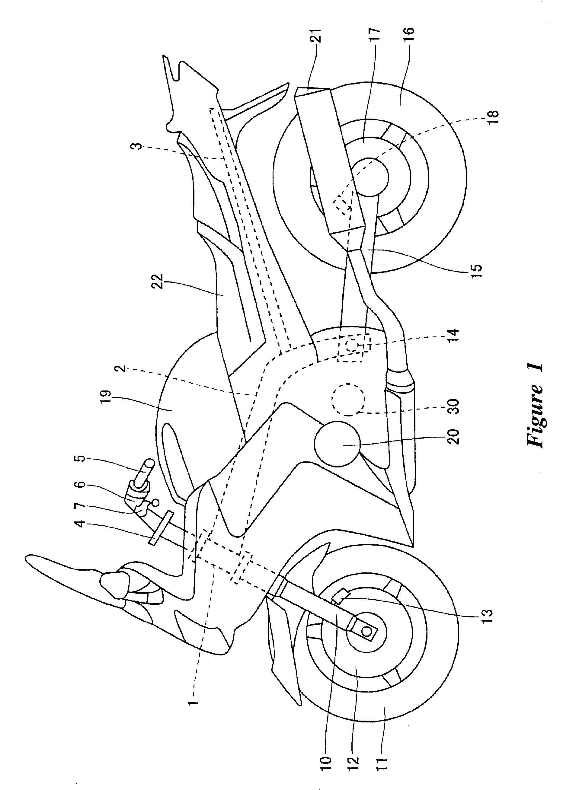
[0058]With reference initially to FIG. 1, a motorcycle (vehicle) is shown that has a clutching system that is arranged and configured in accordance with certain features, aspects and advances of a first embodiment of the present invention. The motorcycle comprises a head pipe 1 that is connected with a forward portion of a main frame 2. The main frame 2 extends downward and rearward from the head pipe 1. A seat rail 3 extends upward from a rear portion of the main frame. The head pipe 1 pivotably supports a steering mechanism portion 4 and a handle 5 can be attached to an upper part of the steering mechanism portion 4.

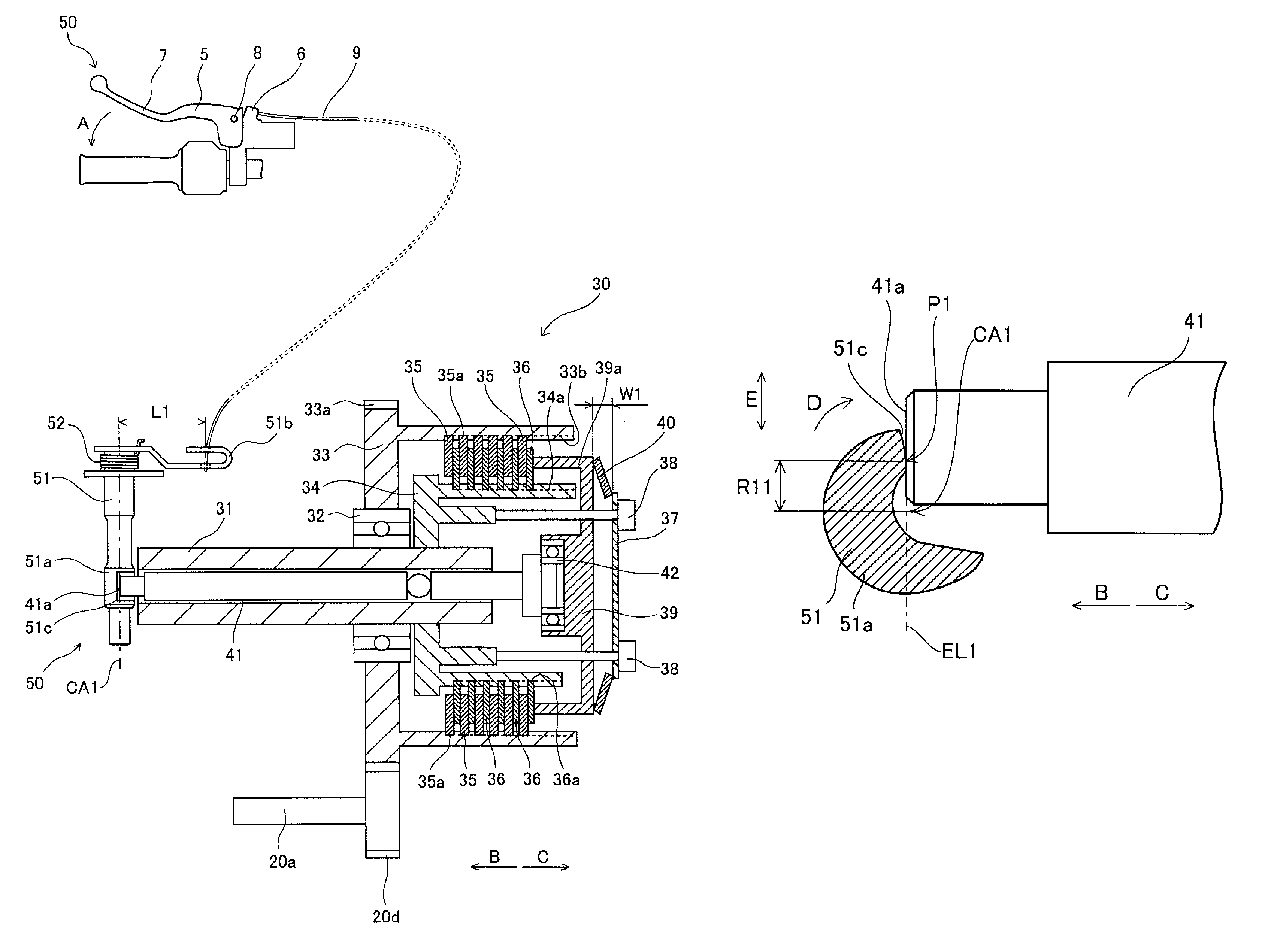
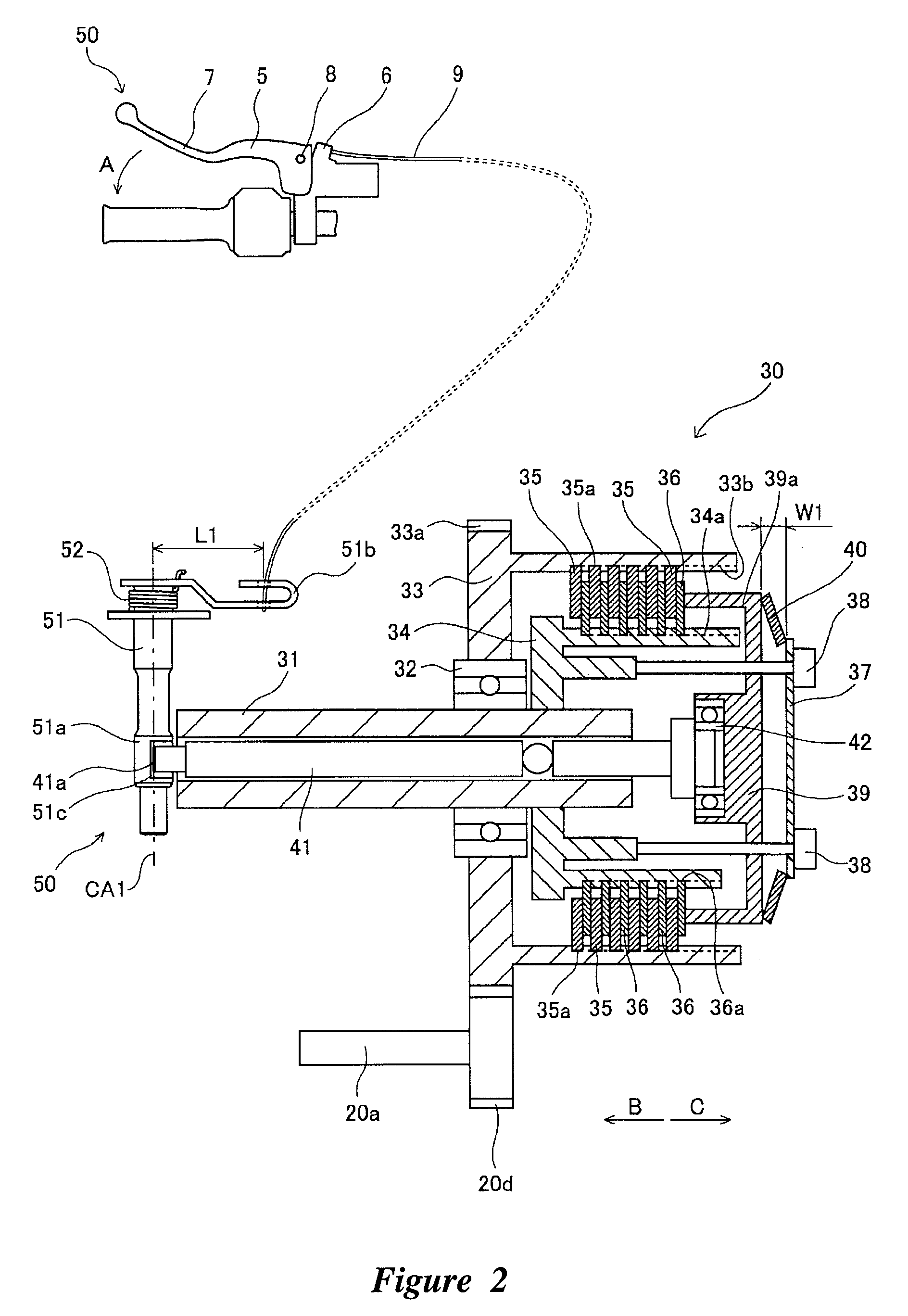
[0059]With reference now to FIG. 2, a holder 6 is secured to the handle 5. A clutch lever 7 is pivotably attached to the holder 6. In the illustrated embodiment, a shaft 8 defines a fulcrum between the clutch lever 7 and the holder 6. A wire 9 connects to the clutch lever 7. At least a portion of the wire 9 is pulled when the clutch lever 7 is pivoted in a first direct...


PUM


Abstract

A clutching system comprises a lever mechanism portion and a clutch mechanism portion. The lever mechanism portion comprises a push lever. The push lever comprises a cam surface. The clutch mechanism portion comprises a push rod. The push rod comprises a cam follower. A Belleville spring functions as a clutch spring. The cam surface and the cam follower are formed such that a lever ratio of the push lever at a pivot start position is larger than a lever ratio of the push lever at a pivot finish position. The Belleville spring is formed such that a force required to move the push lever at the pivot finish position is smaller than a force required to move to the push lever at the pivot start position.

Description

CROSS-REFERENCE TO RELATED APPLICATIONS[0001]This application claims the priority benefit of Japanese Patent Application No. 2005-315541, filed Oct. 31, 2005, which is hereby incorporated by reference in its entirety.BACKGROUND OF THE INVENTION[0002]1. Field of the Invention[0003]The present invention generally relates to a clutch system and a vehicle having the same. In particular, the present invention relates to a clutch comprising a lever mechanism portion and a clutch mechanism portion that is operated by movement of the lever mechanism portion and a vehicle having the same.[0004]2. Description of the Related Art[0005]It is known to disengage a clutch brought by operation of a lever mechanism portion. Operation of the lever mechanism portion is transmitted to a clutch mechanism portion.[0006]A clutch mechanism portion of a clutch includes a plurality of clutch plates (friction plates), an operating plate that presses against the clutch plates, a compression coil spring that urg...

Claims


Application Information

Patent Timeline
Patent Type & Authority Patents(United States)
IPC IPC(8): F16H19/00
CPCF16D25/086
Inventor ISHIDA, YOUSUKEOISHI, AKIFUMIMURAYAMA, TAKUJI
Owner YAMAHA MOTOR CO LTD
Why Eureka
Try Eureka