System for tracking a spatial position of an object via a tracking system

a tracking system and spatial position technology, applied in the field of markers, can solve problems such as calculation errors, emission or light, and navigation system errors, and achieve the effect of reducing or eliminating problems

Inactive Publication Date: 2010-10-26
BRAINLAB
View PDF10 Cites 17 Cited by
  • Summary
  • Abstract
  • Description
  • Claims
  • Application Information

AI Technical Summary

Benefits of technology

[0006]A transparent marker casing can be provided that minimizes or eliminates problems related to substances accumulating on the marker surface. At least portions of the marker casing, and preferably the entire marker casing, can be formed from a transparent material. The transparent material can be transparent to radiation (e.g., optical radiation) that is detected by cameras of a navigation system for determining the position of the markers. The radiation can emanate from the markers due to reflection (passive markers) or emission (active markers) from the makers. The material can be transparent to infrared radiation and / or visible light.
[0008]The marker casing can exhibit a surface that does not accommodate or otherwise pick up liquid, does not absorb liquid, and / or does not attract or hold liquid due to surface tension effects. The marker casing can be formed such that it exhibits a smooth surface, in particular portions can have an even surface. The surface can be formed to be liquid-resistant, in particular hydrophobic. Specifically, the surface and / or the material of the marker casing can be formed from a polymer, from polyvinylchloride, from polyethylene, from polypropylene, polycarbonate or from tetrafluoroethylene or a mixture of the aforementioned. The surface can be hydrosiliconised. The marker casing also can be formed such that it is transparent in the infrared range but not transparent in the visible range. Specifically, the casing can be reflective and / or appear white in the visible light range, so as to enable a practitioner to easily recognize soiling of the marker casing, while infrared radiation emitted and / or reflected by the markers passes through the marker casing.
[0010]The marker casing preferably has a stable, in particular rigid, surface structure to enable easy recognition of surface soils and to enable easy cleaning of the casing. The marker casing can be a preformed structure and can be formed from a thin material, such as a plastic material, for example. Thin, as used herein, means less than 2 millimeters (mm), preferably less than 1 mm, and more preferably less than 0.5 mm. The marker casing can include reinforcements, notches or folds, to stabilize the structure. These reinforcements, notches or folds can be arranged such that they do not interfere with the detection of the markers.
[0014]The marker casing can include a sensor in order to recognize or verify foreign substances that can impair radiation emanating from the markers. In particular, the sensor can be formed such that it can detect or verify the presence of liquids or foreign substances on the surface of the marker casing, such as the outer surface of the marker casing. The sensor can be formed such that when it has verified a foreign substance or a liquid, it outputs a detectable signal, such as an optical or electrical signal. In this way, the navigation system can be warned that radiation emitted from the markers may be impaired. The sensor or the means for verifying moisture or foreign substances also can be formed such that it is optically altered, wherein the observation cameras can detect the alteration. Additional warning electronics can thus be avoided. The surface of the marker casing can be configured such that it changes color when moist (e.g., the marker casing becomes black and / or no longer transparent to the light, such as IR light, when it comes into contact with liquid). This can ensure that incorrect navigation is not performed, since the user or practitioner can immediately recognize that the emission of the markers may be impaired. The user or practitioner can clean the marker casing to remove the soil, thereby restoring proper operation of the markers.

Problems solved by technology

These liquids or soils can alter the emission of light from the markers and, as a result, the navigation system may incorrectly calculate the position of the markers.
In particular, additional reflections may occur on the surface of the liquid, which impair the emission or light, resulting in calculation errors.
In practical medical applications, the multitude of recesses in markers are problematic, as it is difficult for the practitioner (in particular a physician or nurse) to recognize whether the reflections are due to liquid or marks on the marker.
In particular, the recesses spread the liquid out on the surface of the marker and, thus, make it more difficult to determine whether the marker should be cleaned.

Method used


Image

  • System for tracking a spatial position of an object via a tracking system
  • System for tracking a spatial position of an object via a tracking system
  • System for tracking a spatial position of an object via a tracking system

Examples


Embodiment Construction

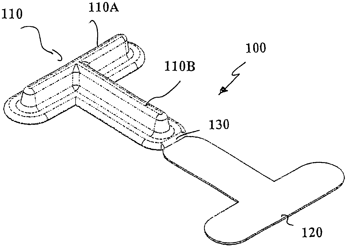
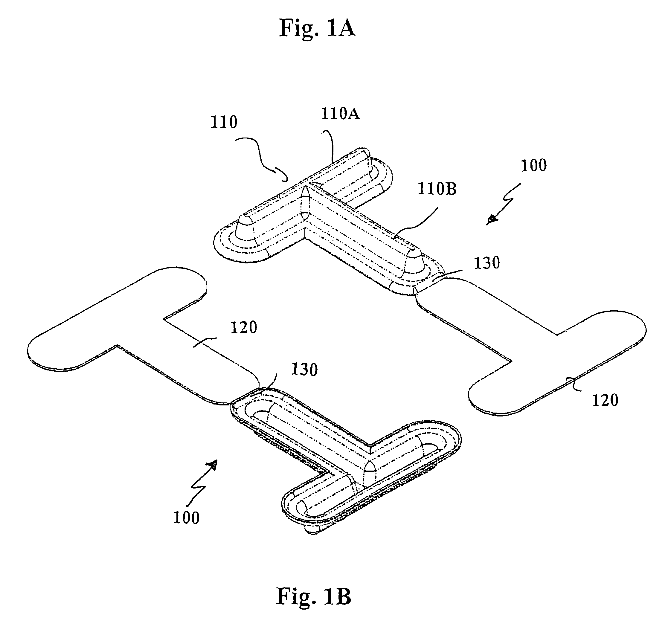
[0022]FIGS. 1A and 1B show a transparent marker casing 100 that includes a T-shaped structure 110 formed by two shell-like longitudinal trenches 110A and 110B, which merge into each other. The shape of the trenches flattens towards an edge. A cover 120 is connected via a hinge 130 to a longitudinal trench110B at the end facing away from the longitudinal trench 110A. The cover is preferably formed flat and / or even and seals the T-shaped opening formed by the two longitudinal trenches 110A and 110B. The longitudinal trenches 110A and 110B represent a recess, in particular a shell-like recess. The marker casing 100, in particular all the components such as the cover 120, the longitudinal trenches 110 and the hinge 130, are preferably formed from polypropylene, such as used for pharmaceutical packaging, for example. The film thickness is preferably less than 1 mm and more preferably less than 500 μm (e.g., 300 μm).

[0023]The marker casing preferably is formed from a film by means of a de...


PUM

PropertyMeasurementUnit
transparentaaaaaaaaaa

Abstract

A transparent marker casing for use with a tracking system, comprising a material that is transparent to radiation emanating from at least one marker, wherein the marker casing is formed such that it at least partially surrounds the at least one marker. The casing can include a moisture sensor that can detect moisture or liquid on a surface of the casing and provide a signal indicative of the presence of moisture.

Description

RELATED APPLICATION DATA[0001]This application claims priority of U.S. Provisional Application No. 60 / 645,397 filed on Jan. 19, 2005, which is incorporated herein by reference in its entirety. European Patent Application No. 04027430.0 is incorporated herein by reference in its entirety.FIELD OF THE INVENTION[0002]The present invention relates to markers used with tracking or navigation systems and, more particularly, to a transparent casing for markers used with medical navigation systems.BACKGROUND OF THE INVENTION[0003]Tracking systems serve to determine and track positions of devices by detecting (e.g. by means of a camera) a position of markers attached to the device. Medical tracking systems serve to determine a position of an instrument or body part with the aid of markers and / or a reference star attached to the instrument / body part (e.g., the reference star can include the markers). The markers can be passive or active markers. Passive markers reflect light, in particular in...

Claims


Application Information

Patent Timeline
Patent Type & Authority Patents(United States)
IPC IPC(8): G01N33/00
CPCA61B19/026A61B19/54A61B19/5244A61B2017/00907Y10T436/13A61B2019/0286A61B2019/5255A61B2019/5483A61B2019/0203A61B2090/3983A61B2050/0051A61B2050/3015A61B2034/2055A61B34/20A61B50/30A61B90/39
Inventor FEILKAS, THOMASHUBER, HANSJORG
Owner BRAINLAB
Why Eureka
Try Eureka