Method for welding on stress-sensitive materials

a stress cracking and welding technology, applied in the field of welding, can solve the problems of reducing the service life of the material, so as to reduce or eliminate post-weld stress corrosion cracking

Inactive Publication Date: 2005-05-17
GENERAL ELECTRIC CO
View PDF5 Cites 2 Cited by
  • Summary
  • Abstract
  • Description
  • Claims
  • Application Information

AI Technical Summary

Benefits of technology

[0004]In accordance with a preferred embodiment of the present invention, there is provided apparatus and methods for welding on stress crack sensitive materials which minimizes or eliminates the problem of stress cracking in the resulting weld. To accomplish the foregoing, hot viscous or plastic weld material is formed on a solid substrate by conventional fusion welding apparatus, typically including a heat source, and which may include the addition and melting of filler material as well as melting of a portion of the substrate. The process includes simultaneous hot compression with or without concurrent heat sinking of the weld. Preferably, compression force and heat sinking are simultaneously applied to the hot weld deposit during progression of the weld pass.
[0005]More particularly, plastic deformation of the hot weld metal is provided by controlled contact with a compression tool. External cooling, in addition to the inherent internal conduction to the hot surrounding material, is simultaneously provided to the weld area by contact with the conductive end of the compression tool, while the pressure of the compression tool is maintained against the weld pool. The predetermined compression and external heat sinking conditions are maintained on the weld area until the weld material is known or measured to be below its predetermined hot crack sensitive temperature or until the residual stress is sufficiently low to preclude in-service cracking. Additional cooling may be applied once outside the range of temperatures at which hot cracking is anticipated to occur, with the result that the weld surface has reduced tensile and preferably compressive stresses.
[0006]The foregoing method is also applicable to minimizing or eliminating post-weld stress corrosion cracking. By plastically compressively stressing the hot weld material when the hot weld material lies within a predetermined temperature range corresponding to the hot crack-sensitive predetermined temperature range, any tendency toward stress corrosion cracking in the completed weld is minimized or eliminated.
[0009]In a further preferred embodiment according to the present invention, there is provided a method of welding materials while the materials are in a predetermined temperature range to minimize or eliminate post-weld stress corrosion cracking comprising the steps of (a) forming hot metal weld material on a portion of a substrate, (b) plastically compressively stressing the hot metal weld material from an external source while the temperature of the hot metal weld material lies substantially within the predetermined temperature range and (c) performing step (b) until the temperature of the weld material is below the predetermined temperature range or until residual stresses are sufficiently low to minimize or preclude stress corrosion cracking in the completed weld.
[0010]In a further preferred embodiment according to the present invention, there is provided a method of welding materials while the materials are in a predetermined temperature range to minimize or eliminate post-weld stress corrosion cracking comprising the steps of (a) forming hot metal weld material on a portion of a substrate, (b) simultaneously plastically compressively stressing and cooling the hot metal weld material from an external source while the temperature of the hot metal weld material lies substantially within the predetermined temperature range and (c) performing step (b) until the temperature of the weld material is below the predetermined temperature range or until residual stresses are sufficiently low to minimize or preclude cracking in the completed weld.

Problems solved by technology

Materials, however, are oftentimes sensitive to hot cracking.
In neutron irradiated austenitic stainless steels with significant boron content (which is susceptible to transmutation to helium), the helium in the weld materials causes several adverse effects through changes in mechanical properties.
For example, when high helium content materials are exposed to the heat of a welding cycle, the high temperature allows the helium to diffuse rapidly to grain boundaries which form voids which, in turn, weaken the material resulting in hot cracking.
Even for known low heat input fusion welding processes, the capability to reliably weld without hot cracking is limited to materials having relatively low helium levels.
The hot cracking problem is also compounded by the typically high tensile temporal and residual surface stresses caused by the fusion processes.
This adverse stress situation in the as-welded condition is characteristic of all conventional fusion welding processes and applications, especially for the heavy section thicknesses of materials generally found in permanent nuclear vessel internals and for the vessel wall itself or its attachments.
It is effectively impossible to provide sufficiently low heat in the fusion welding process to avoid hot cracking, while still having a viable fusion welding process.
In addition to the hot cracking problem during cooling of the weld pool, stress corrosion cracking (SCC) can occur in materials susceptible to thermal or neutron sensitization when used in aggressive environments such as oxygen or halogen containing high temperature nuclear reactor water or moderator.
This type of environmentally induced cracking occurs when the level of surface residual stress becomes sufficiently tensile as is typically the case for conventional fusion welding practice.

Method used


Image

  • Method for welding on stress-sensitive materials
  • Method for welding on stress-sensitive materials
  • Method for welding on stress-sensitive materials

Examples


Embodiment Construction

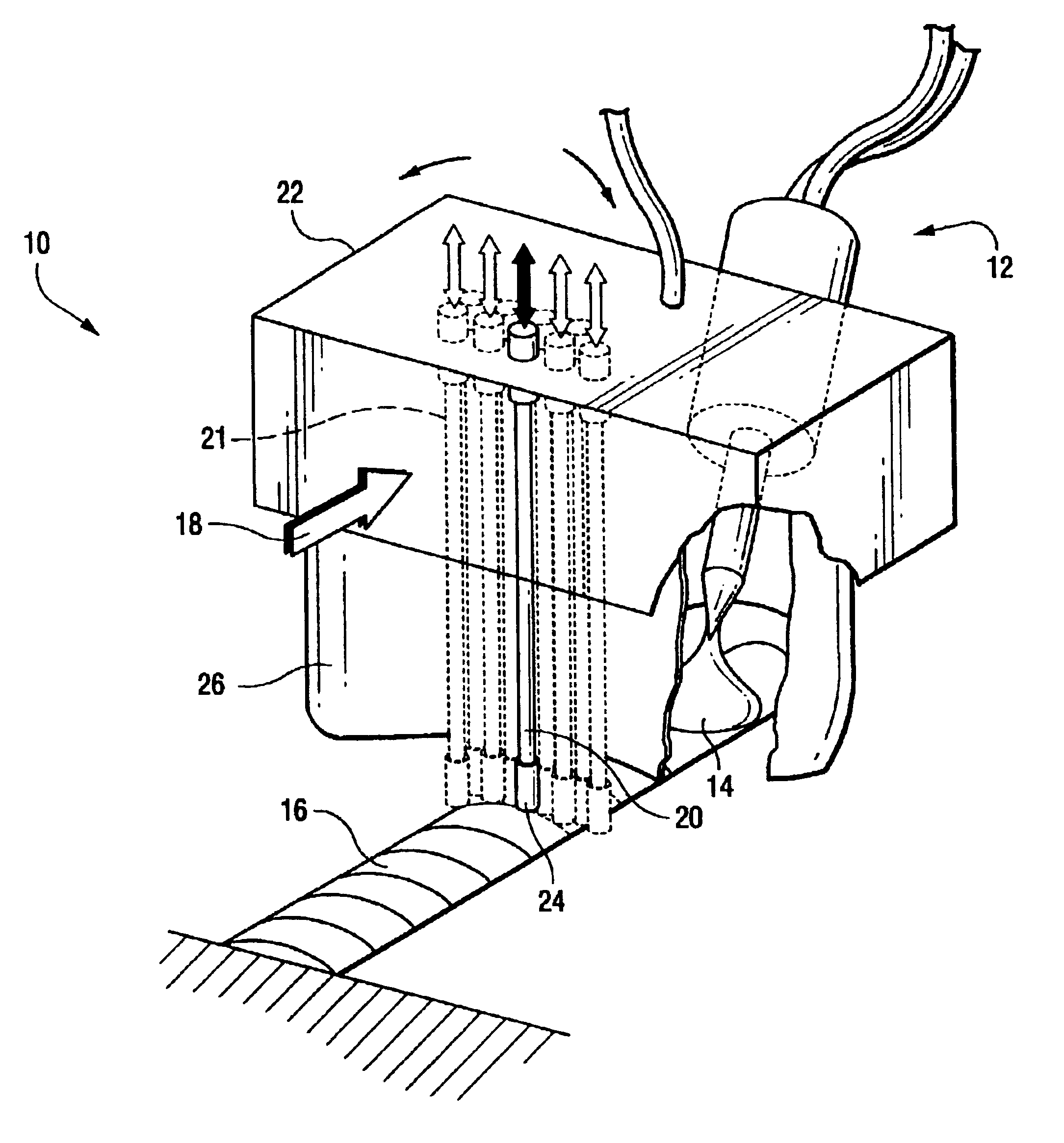
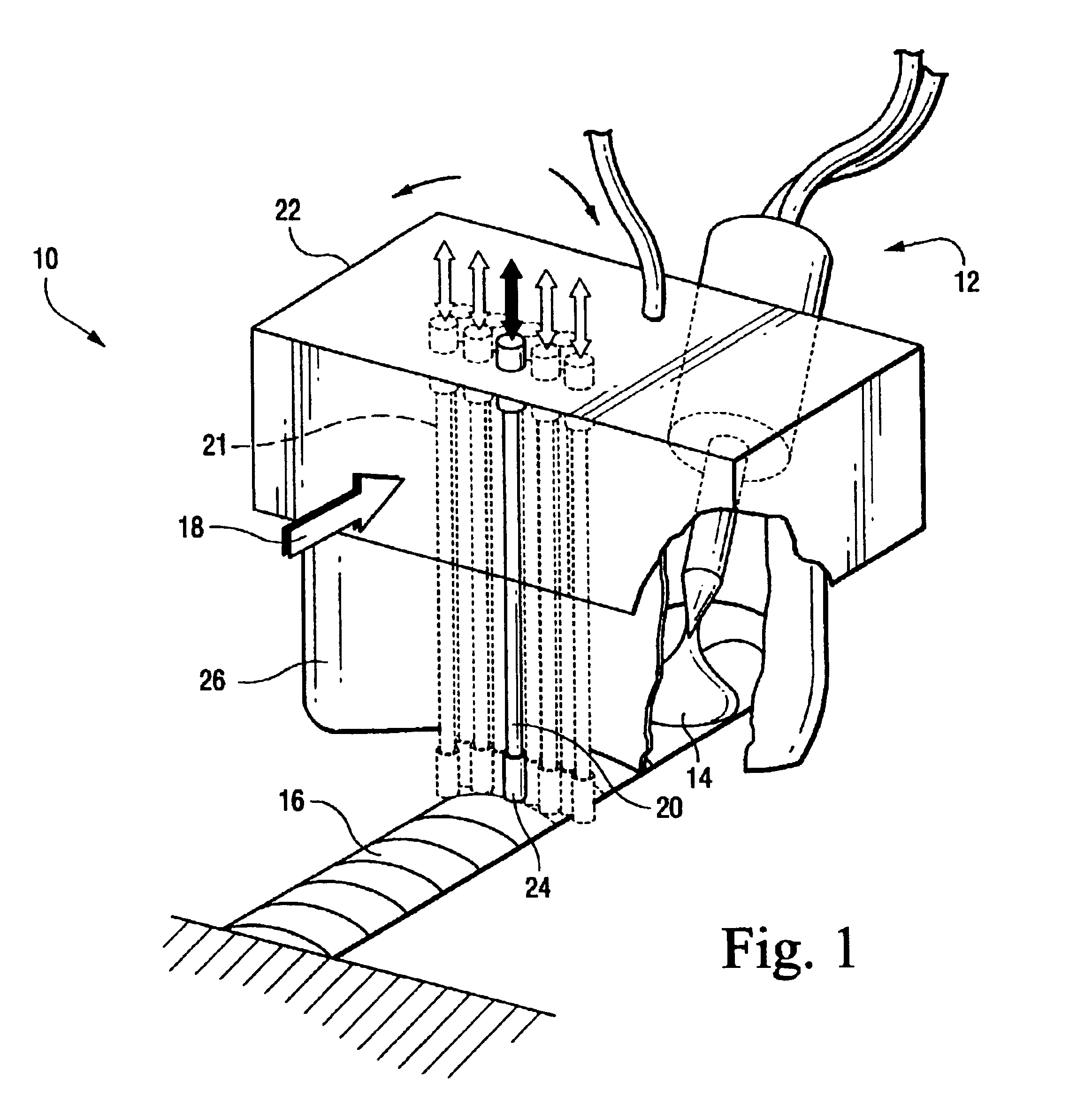
[0021]Referring now to the drawings, particularly to FIG. 1, there is illustrated a combined compression and heat sinking tool generally designated 10 in conjunction with a welding heat source generally indicated 12. The welding heat source may be any type of fusion welding heat source; for example, electric arc, laser beam or electron beam and with or without added weld material. The heat source 12 is illustrated forming, with or without added weld material, a weld pool 14 eventually forming a weld bead 16. The weld bead 16 may be applied at the juncture of two adjoining parts to secure the parts one to the other, or may be provided in an overlying manner to a surface to provide a cladding. It will be appreciated from a review of FIG. 1 that the direction of the welding is in the direction of the arrow 18.

[0022]Tool 10 includes a multiple element compression tool 21 comprising a plurality of pins or needles 20 carried by a housing 22. By means not shown, the needles or pins 20 are ...


PUM

PropertyMeasurementUnit
temperatureaaaaaaaaaa
residual stressesaaaaaaaaaa
stress corrosion crackingaaaaaaaaaa

Abstract

For stress-crack-sensitive materials, a weld pool is formed on a substrate. The weld pool is simultaneously plastically strained and cooled while the temperature of the hot metal weld pool lies substantially within a predetermined range in which hot cracking typically occurs. The hot metal is plastically strained and cooled until the temperature of the weld material is below the predetermined temperature range associated with hot cracking or until residual stresses in the weld are sufficiently low to preclude cracking in the completed weld.

Description

BACKGROUND OF THE INVENTION[0001]The present invention relates generally to welding and particularly to welding on stress-crack sensitive materials to reduce or eliminate hot cracking and reduce or eliminate stress corrosion cracking.[0002]There are various types of conventional fusion welding processes, such as electric arc, laser beam, or electron beam welding. In those processes, a molten pool of hot metal is formed, either by melting a substrate or adding a filler metal, or both. Materials, however, are oftentimes sensitive to hot cracking. Hot cracking of the welded surface is typically caused by strains and stresses due to contraction on cooling, i.e., during the phase change from liquid hot metal to a solid state. An extreme but actual example of hot cracking sensitive materials is fusion welding on material containing higher levels of helium, such as in permanent portions of older nuclear reactor vessel internals near the fuel core. In neutron irradiated austenitic stainless...

Claims


Application Information

Patent Timeline
Patent Type & Authority Patents(United States)
IPC IPC(8): B23K26/42B23K26/32B23K10/02B23K15/00B23K26/00B23K26/24B23K31/02B23K9/00B23K9/32C21D9/50C21D7/04C21D7/00B23K31/00
CPCB23K9/0026B23K9/0061B23K9/32B23K10/02B23K15/0006B23K15/0026C21D9/505B23K26/24B23K26/3206B23K26/422B23K31/02B23K15/0046C21D7/04B23K26/32B23K26/702B23K2103/50
Inventor OFFER, HENRY PETER
Owner GENERAL ELECTRIC CO
Why Eureka
Try Eureka