Froth handling pump

a technology of froth handling and froth pump, which is applied in the direction of priming pump, machine/engine, liquid fuel engine, etc., can solve the problems of reducing pump performance, affecting the performance of the pump, and affecting the flow and head of the pump, so as to achieve the effect of reducing or eliminating the problem

Inactive Publication Date: 2010-03-11
GIW IND
View PDF18 Cites 8 Cited by
  • Summary
  • Abstract
  • Description
  • Claims
  • Application Information

AI Technical Summary

Benefits of technology

[0005]The present invention is directed to a froth handling pump, which significantly minimizes or eliminates the problems described herein during bitumen froth pumping. As used herein, “bitumen” refers to any of various flammable mixtures of hydrocarbons and other substances, occurring naturally or obtained by distillation from coal or petroleum.

Problems solved by technology

While bitumen froth is widely pumped and much is known about the process, a number of problems exist with froth pumps themselves and the pumping process.
First, bitumen froth pumps often “air lock.” This occurs when gasses accumulate in the suction of the pump under the action of the centrifugal forces operating on the fluid in the passages of a rotating impeller to form a bubble which partially blocks the suction and significantly degrades pump performance (as much as 40% to 70% loss in both flow and head).
With viscous flows like bitumen, this air lock can be particularly difficult to remedy due to the laminar, or near laminar, nature of the high viscosity flow.
Second, bitumen froth pumps cannot typically produce more than about 30 to 40 m of head, which is limited by the high viscosity of the bitumen and by the maximum speed at which the pump can be run before net positive suction head available (NPSHA) available to the pump suction falls below the minimum required to prevent cavitation in the pump impeller.

Method used


Image

  • Froth handling pump
  • Froth handling pump
  • Froth handling pump

Examples


Embodiment Construction

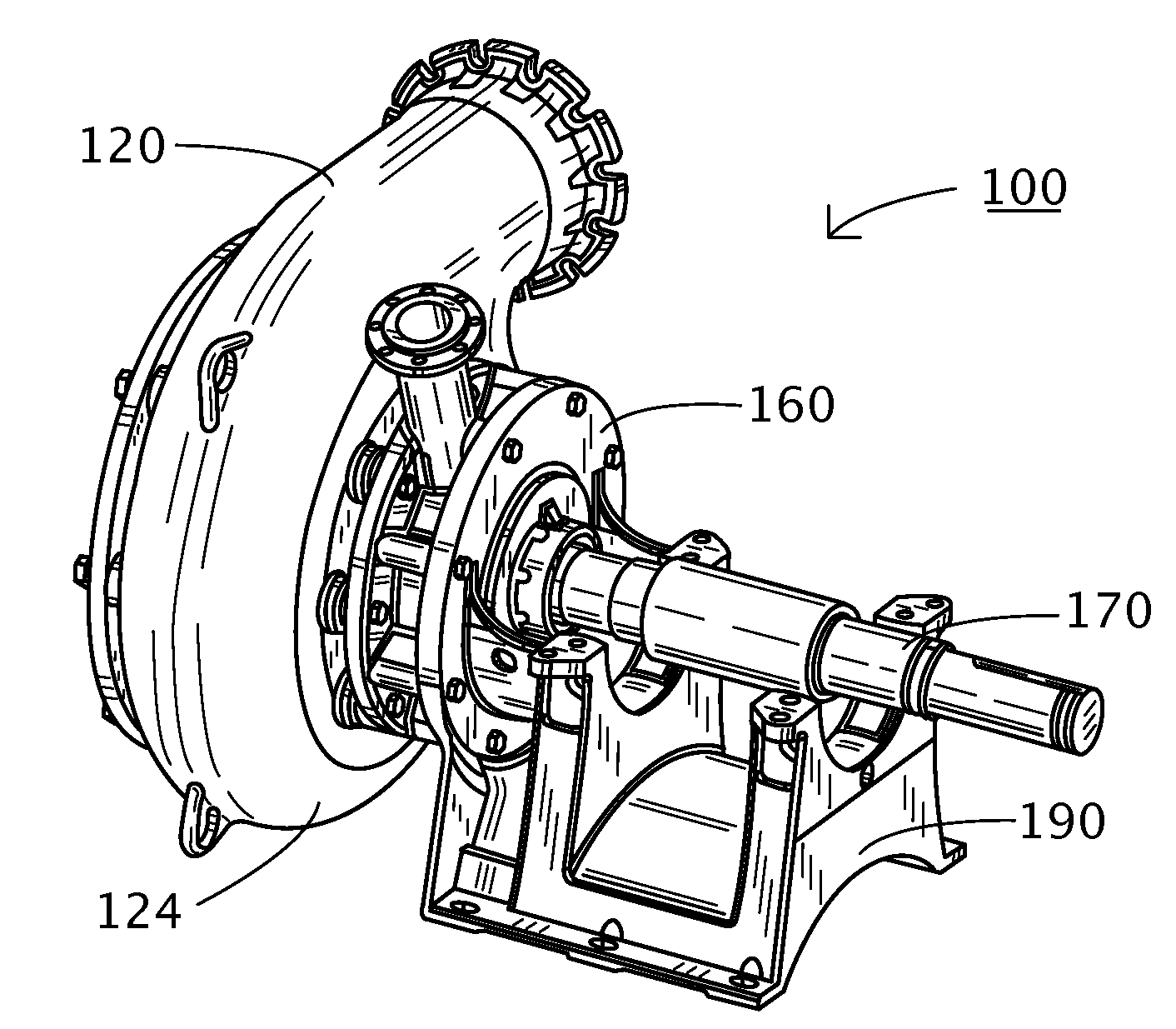
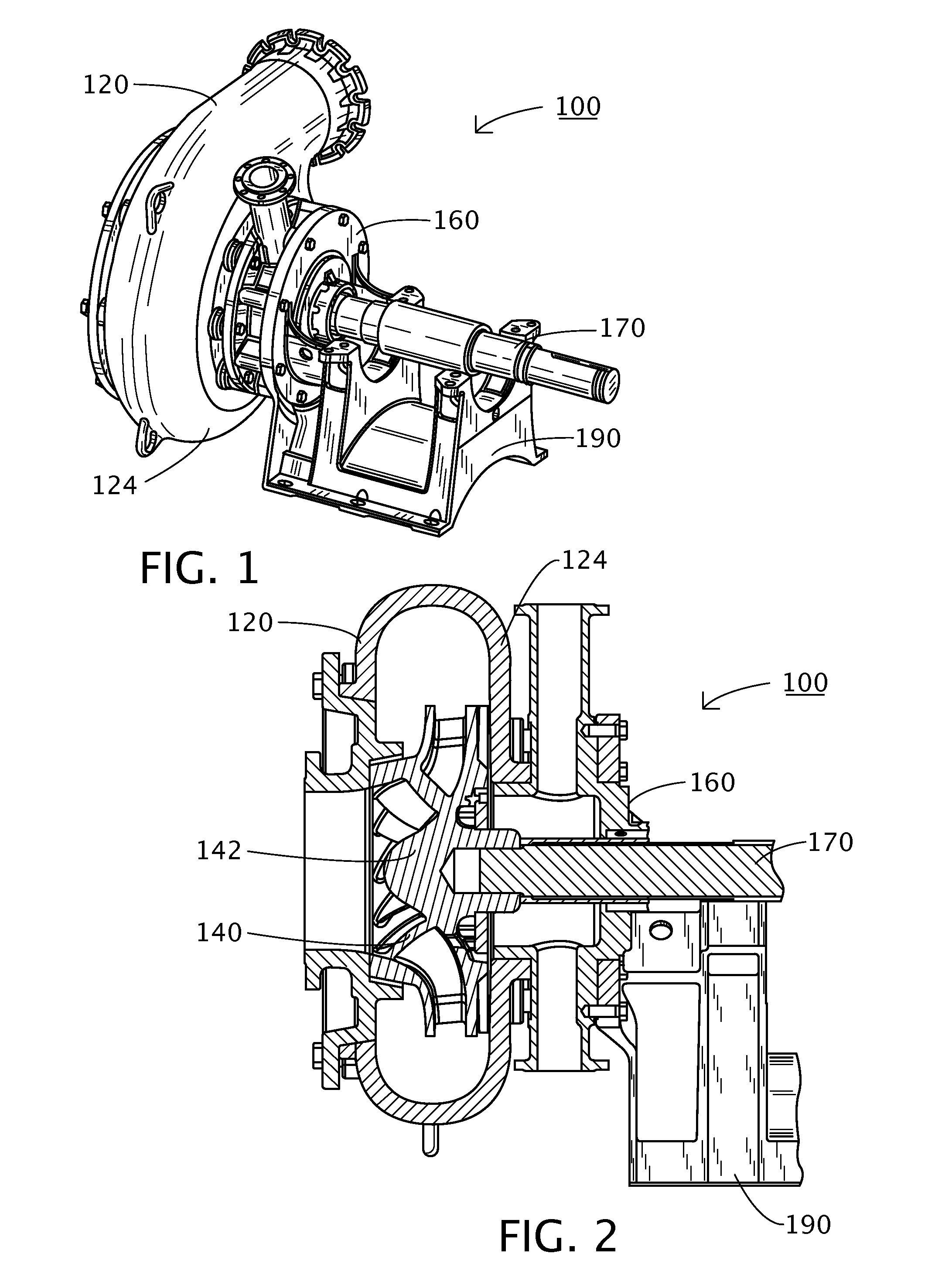
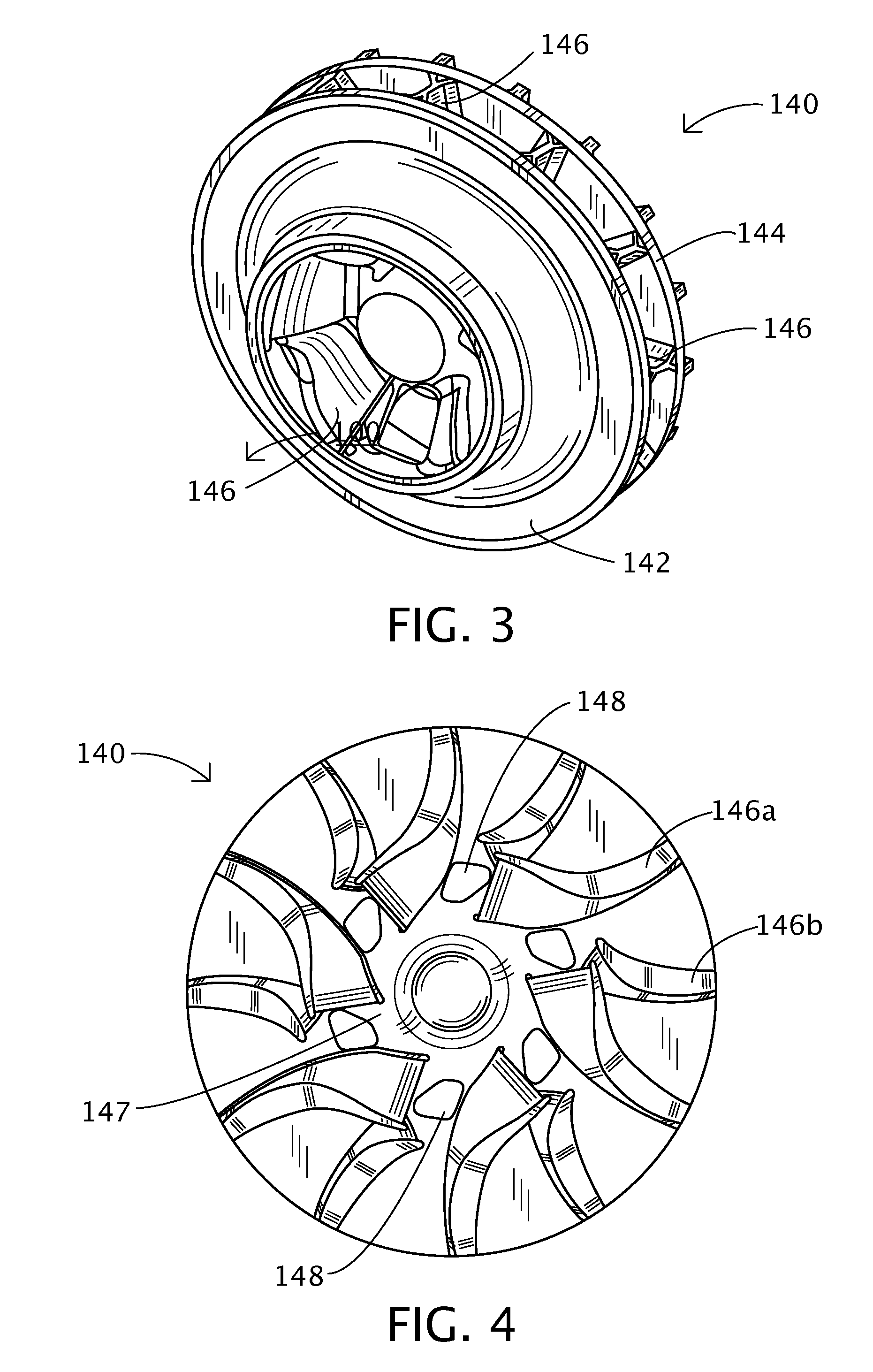
[0019]Referring to the Figures in general, and FIGS. 1 and 2 in particular, the froth handling pump of the present invention is shown generally as 100. In its simplest embodiment, the froth handling pump 100 comprises a centrifugal pump casing 120, a novel impeller 140 mounted in the casing, and a de-aeration chamber 160 mounted to the rear side 124 of the pump casing 120. A conventional pump shaft 170 passes through the de-aeration chamber 160 and attaches to the hub 142 of the impeller 140. The shaft 170 is then mounted on a conventional pedestal 190 via a conventional bearing arrangement (not shown).

[0020]As shown in FIG. 2, the pump casing 120 of the froth pump of the present invention is a conventional design for centrifugal slurry pumps; however, a modified, or more open inlet side may be contemplated for a particular froth handling application. Nonetheless, the froth handling pump 100 described herein eliminates the need for a casing or shroud modification.

[0021]Referring to ...


PUM


Abstract

A froth handling pump is provided which includes a pump casing, an impeller mounted within the casing, and a de-aeration chamber mounted to the rear side of the pump casing. The impeller comprises multiple pumping vanes, each of the vanes having an inlet angle and an outlet angle, wherein the outlet angle is greater than the inlet angle, the outlet angles terminating at a rear shroud. The rear shroud includes multiple vent holes for the passage of gasses therethrough. The de-aeration chamber, which comprises an inner volume, includes an inlet formed on the inner side for receiving gasses passing through the plurality of vent holes. At least one vent outlet is provided for the discharge of gasses from the de-aeration chamber.

Description

FIELD OF THE INVENTION[0001]The present invention relates to the field of centrifugal slurry pumps, and particularly, to froth pumps for handling bitumen froth.BACKGROUND OF THE INVENTION[0002]Centrifugal pumps, as the name implies, employ centrifugal force to lift liquids from a lower to a higher level or to produce a pressure. This type of pump, in its simplest form, comprises an impeller consisting of a connecting hub with a number of vanes and shrouds, rotating in a volute collector or casing. Liquid drawn into the center, or eye, of the impeller is picked up by the vanes and accelerated to a high velocity by rotation of the impeller. It is then discharged by centrifugal force into the casing and out the discharge branch of the casing. When liquid is forced away from the center of the impeller, a vacuum is created and more liquid flows into the center of the impeller. Consequently there is a flow through the pump. There are many forms of centrifugal pumps, including the type use...

Claims


Application Information

Patent Timeline
Patent Type & Authority Applications(United States)
IPC IPC(8): F04D29/00F04D17/16F04D29/30F04D29/42
CPCF04D7/04F04D29/2277F04D9/003
Inventor VISINTAINER, ROBERT J.HERGT, PETERRAVISUNDAR, THILLAINATARAJANJAEGER, CHRISTOPH
Owner GIW IND
Why Eureka
Try Eureka