Ionizer mounting structure for a vehicle air conditioning system

a technology for air conditioning systems and ionizers, which is applied in the direction of magnetic separation, discharge tube main electrodes, transportation and packaging, etc., can solve the problems of inconvenient and difficult to remove the ionizer, and difficult to insert tools and loose screws, etc., to achieve quick repair and replacement of the ionizer, easy and convenient demounting, and convenient and fast mounting of the ionizer

Active Publication Date: 2010-11-02
HANON SYST
View PDF26 Cites 14 Cited by
  • Summary
  • Abstract
  • Description
  • Claims
  • Application Information

AI Technical Summary

Benefits of technology

[0013]In view of the above-noted problems inherent in the prior art, it is an object of the present invention to provide an ionizer mounting structure for a vehicle air conditioning system that enables an ionizer to be removed and mounted in an easy and simple manner.
[0014]Another object of the present invention is to provide an ionizer mounting structure for a vehicle air conditioning system that can improve the workability in maintenance and repair.
[0015]A further object of the present invention is to provide an ionizer mounting structure for a vehicle air conditioning system that can prevent electric connection between first and second discharge electrodes, which would otherwise be caused by ambient moisture.

Problems solved by technology

However, the conventional air conditioning system referred to above poses a problem in that it is very difficult to separate the ionizer 40 when the ionizer 40 is removed from the air conditioning case 10 to repair or replace the same.
This makes it difficult to insert a tool and loosen the screws 42b.
Even after the screws 42b are loosened and removed, it is very inconvenient and difficult to demount the ionizer 40 from the air conditioning case 10.
Consequently, the conventional air conditioning system is problematic in that it is very difficult to detach the ionizer 40 from the air conditioning case 10 and to attach the same to the air conditioning case 10.
This leads to a drawback in that the moisture condensed in and around the upper first discharge electrode 44 flows toward the lower second discharge electrode 46.
Such a drawback poses a problem in that the first and second discharge electrodes (44, 46) may be electrically connected to each other.
The electrical connection may cause a spark between the first and second discharge electrodes (44, 46), consequently generating a discharge noise.

Method used


Image

  • Ionizer mounting structure for a vehicle air conditioning system
  • Ionizer mounting structure for a vehicle air conditioning system
  • Ionizer mounting structure for a vehicle air conditioning system

Examples


Embodiment Construction

[0033]A preferred embodiment of an ionizer mounting structure for a vehicle air conditioning system in accordance with the present invention will now be described in detail with reference to the accompanying drawings. In the following description, the same reference numerals as used in describing the prior art will be used to designate the same elements as those of the prior art.

[0034]Prior to describing the ionizer mounting structure in accordance with the present invention, a general aspect of an ionizer of a vehicle air conditioning system will be described with reference to FIGS. 3 and 4.

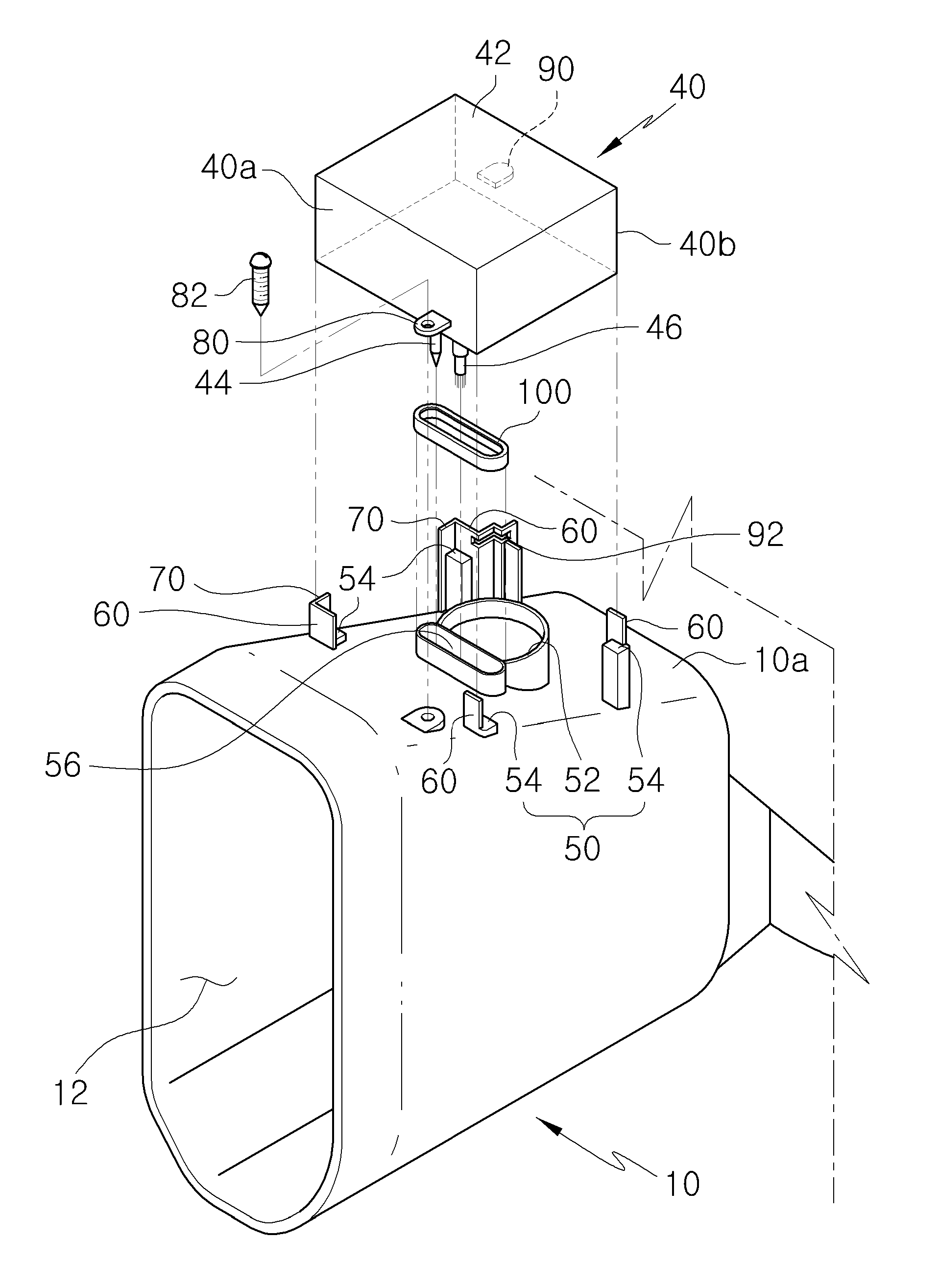
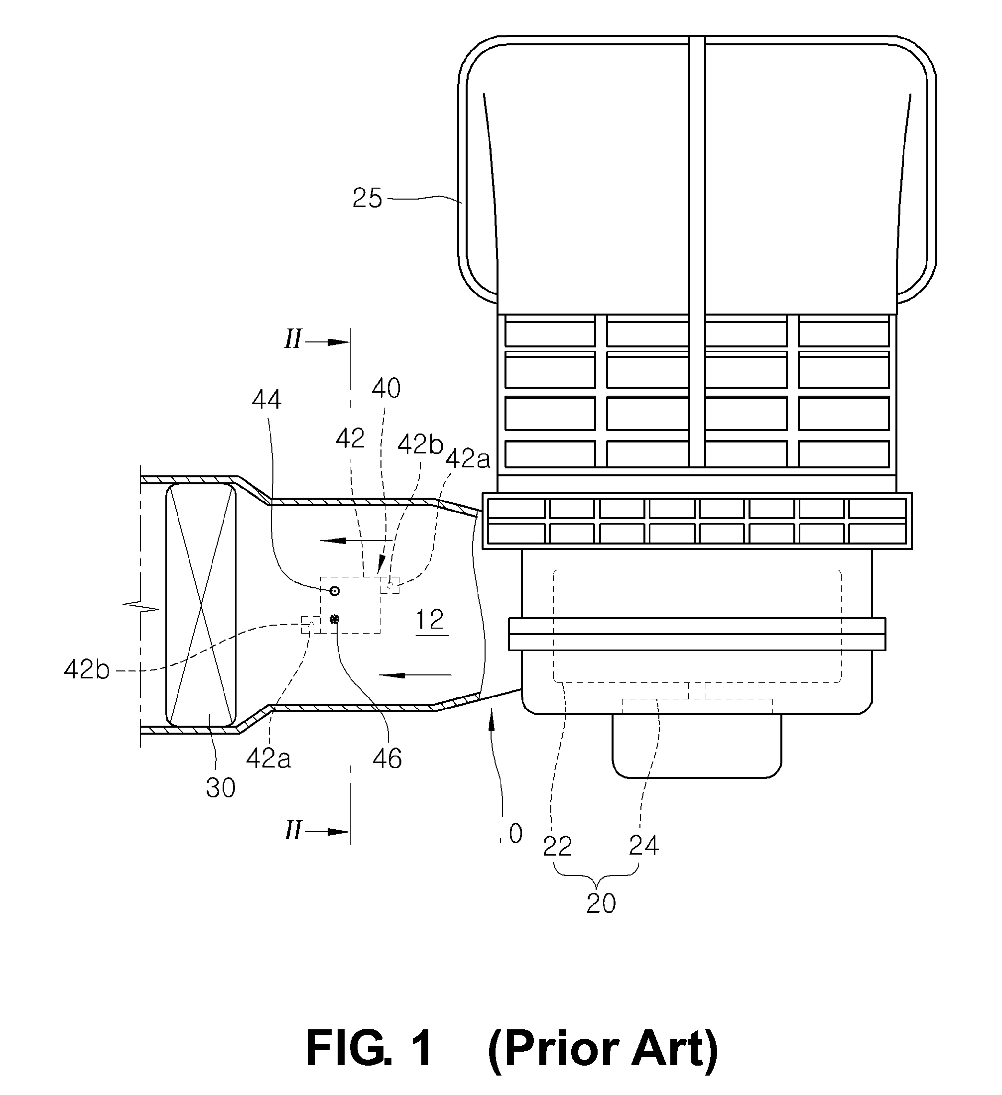
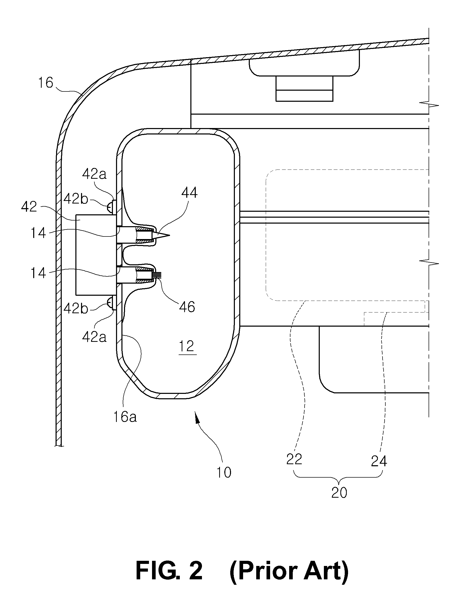
[0035]The ionizer 40 includes a main body 42 attached to an upper surface of an air conditioning case 10. The main body 42 has a rectangular box shape and includes first and second discharge electrodes (44, 46) arranged in a spaced-apart relationship with each other.

[0036]The first and second discharge electrodes (44, 46) extend into an internal passageway 12 of the air conditioning case 10 and ...


PUM


Abstract

The present invention relates to an ionizer mounting structure for a vehicle air conditioning system. The air conditioning system includes an air conditioning case having an internal passageway and an ionizer for generating negative ions and positive ions within the internal passageway. The air conditioning case has a discharge electrode insertion hole and the ionizer has a plurality of discharge electrodes extending into the internal passageway through the discharge electrode insertion hole. The ionizer mounting structure includes a mounting and demounting structure for allowing the ionizer to be mounted to the air conditioning case through sliding movement from a demounting position on a passenger room side to a mounting position above the air conditioning case and for allowing the ionizer to be demounted from the air conditioning case through sliding movement from the mounting position to the demounting position.

Description

FIELD OF THE INVENTION[0001]The present invention relates to an ionizer mounting structure for a vehicle air conditioning system and, more particularly, to an ionizer mounting structure for a vehicle air conditioning system that enables an ionizer to be mounted and removed with ease, thereby improving the ease of maintenance when repairing and replacing the ionizer.BACKGROUND OF THE INVENTION[0002]An automotive vehicle is provided with an air conditioning system for controlling the temperature of a vehicle room air. As shown in FIG. 1, a conventional air conditioning system includes an air conditioning case 10 in which a blower 20 is installed. In general, the air conditioning case 10 is arranged inside of an instrument panel in front of a passenger seat.[0003]The blower 20 includes a blower fan 22 and a blower motor 24 for driving the blower fan 22. The blower 20 serves to inhale an external air or an internal air and then to feed the inhaled air to an internal passageway 12 of the...

Claims


Application Information

Patent Timeline
Patent Type & Authority Patents(United States)
IPC IPC(8): B03C3/40
CPCB03C3/82B60H3/0071B03C2201/28B03C2201/30
Inventor KANG, SUNG HOBYON, SANG CHULSEO, YONG EUN
Owner HANON SYST
Why Eureka
Try Eureka