Method for manufacturing display device comprising separated and electrically connected source wiring layers

a manufacturing method and display device technology, applied in the field of display devices, can solve the problems of reducing the number of light-exposure masks whose design and manufacturing cost is high, and achieve the effects of low cost, high reliability, and simplified photolithography process

Inactive Publication Date: 2010-11-02
SEMICON ENERGY LAB CO LTD
View PDF17 Cites 19 Cited by
  • Summary
  • Abstract
  • Description
  • Claims
  • Application Information

AI Technical Summary

Benefits of technology

[0007]As noticed in the above-described Patent Documents, a photolithography process is comprised of formation of a photo resist, light-exposure treatment with the use of a light-exposure mask, development, and the like. Further, the photolithography process is a process which also can be comprised of a large number of steps, such as washing treatment, a test, and the like, in addition to the above-described steps, and is a one of factors that have influence on manufacturing cost, a yield, productivity, and the like. Particularly, reducing the number of light-exposure masks whose design and manufacturing cost is high is a major problem.
[0008]In view of the above-described problem, it is one object of the present invention to manufacture a display device with high reliability at low cost while reducing the number of light-exposure masks and simplifying a photolithography process.
[0011]Since a mask layer formed with the use of a multi-tone mask has a plurality of film thicknesses, and can be changed in shape by performing ashing, the mask layer can be used in a plurality of etching steps for processing into different patterns. Therefore, a mask layer corresponding at least two kinds or more of different patterns can be formed by one multi-tone mask. Thus, the number of light-exposure masks can be reduced and the number of corresponding photolithography steps can be also reduced, whereby simplification of a process can be realized.
[0012]As conductive layers for the gate wiring layer, source wiring layers, and the source and drain electrode layers, a conductive material having reflectivity to light is used. On the other hand, as the substrate and the pixel electrode, a material having light-transmitting property is used. In a light-exposure step to form the mask layers used for an etching step of an insulating film functioning as a protective film of a thin film transistor, the substrate is irradiated with light from the opposite side of the surface over which elements are formed (also referred to as the back side), and light exposure from the back surface can be performed using conductive layers having reflectivity used for the gate wiring layer, the source wiring layers, and the source and drain electrode layers, as masks. Therefore, since it is not necessary to form a light-exposure mask for etching of the insulating film, the number of photolithography steps can be further reduced.
[0015]Therefore, the photolithography process can be simplified by reducing the number of light-exposure masks, whereby a display device with high reliability can be manufactured at low cost with high productivity.
[0018]According to the present invention, the photolithography process can be simplified by reducing the number of light-exposure masks, whereby a display device with high reliability can be manufactured at low cost with high productivity.

Problems solved by technology

Particularly, reducing the number of light-exposure masks whose design and manufacturing cost is high is a major problem.

Method used


Image

  • Method for manufacturing display device comprising separated and electrically connected source wiring layers
  • Method for manufacturing display device comprising separated and electrically connected source wiring layers
  • Method for manufacturing display device comprising separated and electrically connected source wiring layers

Examples


embodiment mode 1

[0033]In this embodiment mode, a display device including a thin film transistor and a manufacturing method thereof will be described with reference to FIGS. 1A to 1C, FIGS. 2A to 2C, FIGS. 3A to 3D, FIGS. 4A to 4D, FIGS. 5A to 5D, FIGS. 6A to 6C, and FIGS. 7A and 7B.

[0034]An n-channel thin film transistor has higher mobility than p-channel thin film transistor. Therefore, an n-channel thin film transistor is more suitable for a driver circuit than a p-channel thin film transistor. However, in the present invention, either an n-channel thin film transistor or a p-channel thin film transistor may be employed. With any polarity of a thin film transistor, it is preferable that all the thin film transistors formed over one substrate have the same polarity so that the number of manufacturing steps is reduced. Here, description is made using an n-channel thin film transistor.

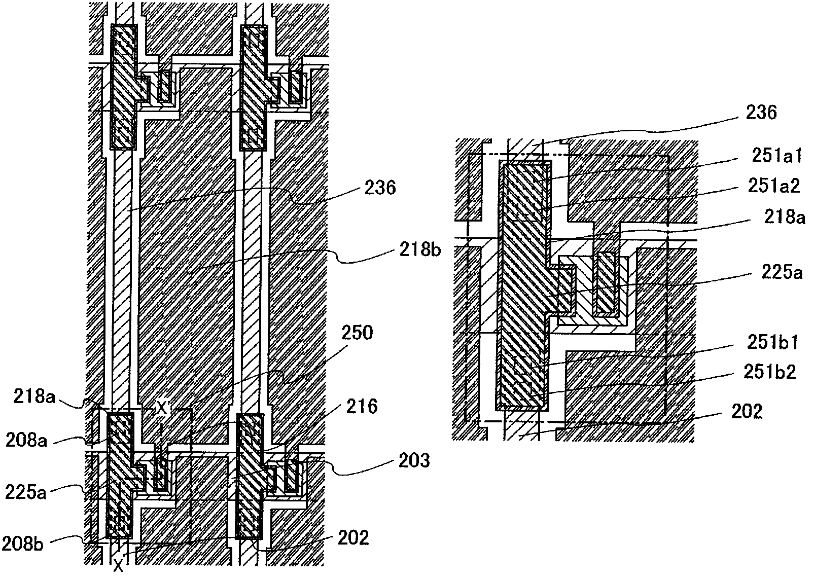
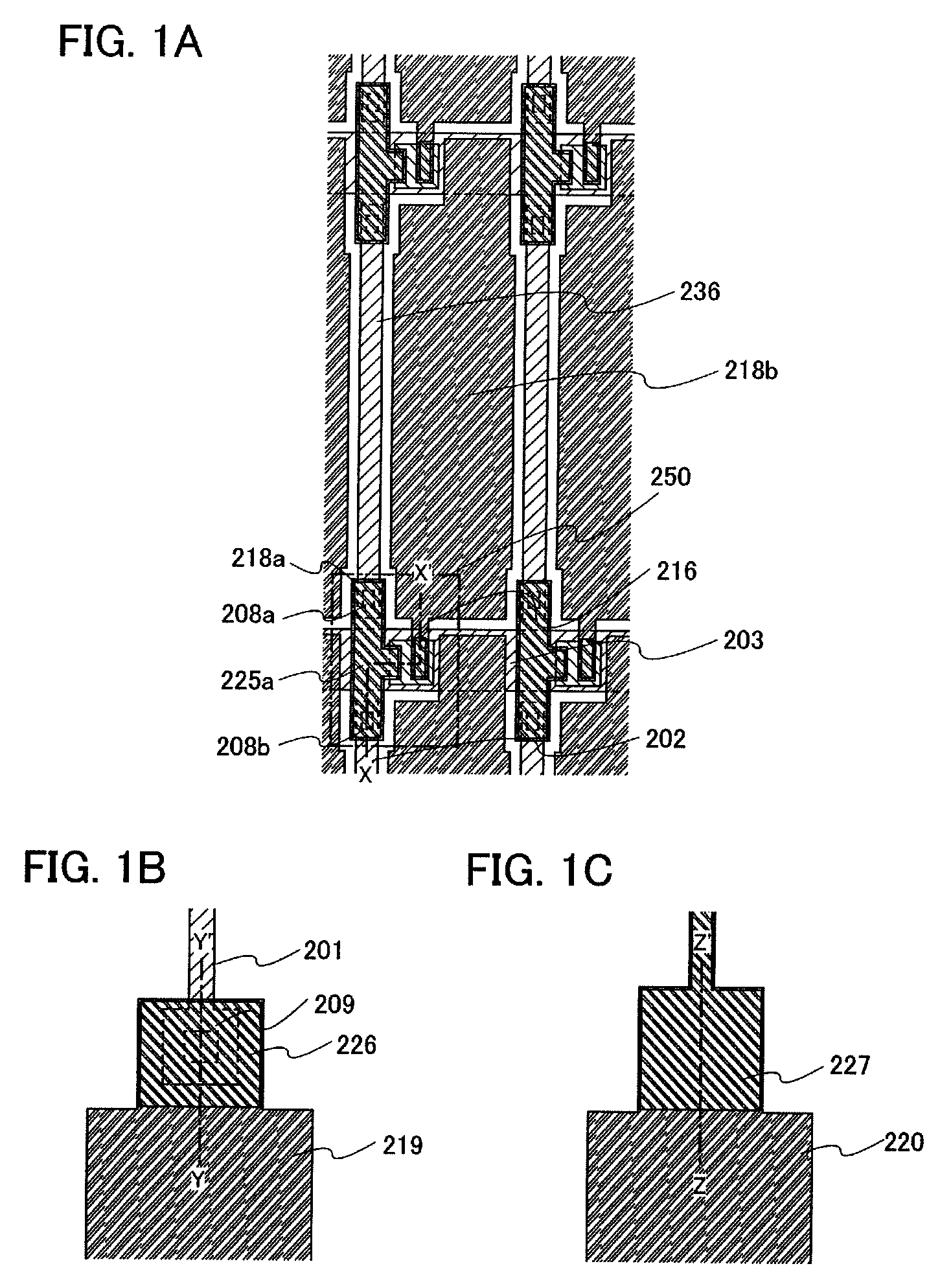
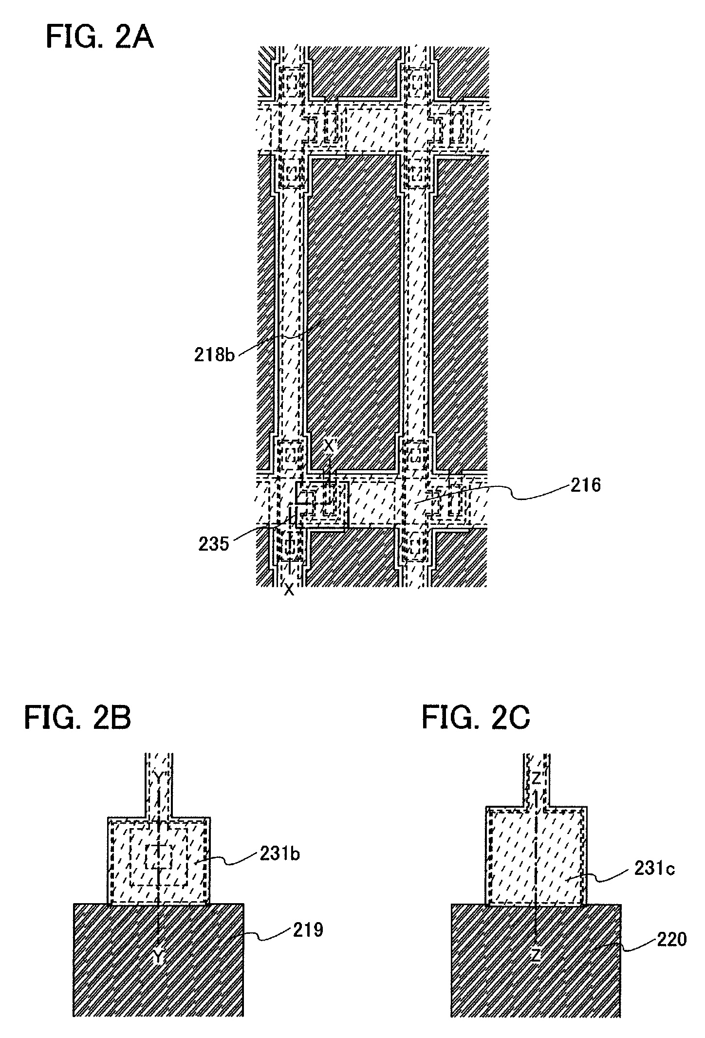
[0035]FIGS. 1A to 1C and FIGS. 2A to 2C show an example of a plane view which illustrates a display device includin...

embodiment mode 2

[0097]In this embodiment mode, an example of a thin film transistor whose shape is different from that of Embodiment Mode 1 will be described. Except the shape, the thin film transistor can be formed in a similar manner to Embodiment Mode 1; thus, repetitive description of the same components or components having similar functions as in Embodiment Mode 1 and a manufacturing process for forming those components will be omitted.

[0098]A thin film transistor 240 of this embodiment mode, which is an inversed staggered thin film transistor with a channel-etched structure, is shown in FIG. 8.

[0099]In FIG. 8, over a substrate 248a, thin film transistor 240 is provided, which includes a gate electrode layer 241, a gate insulating layer 242, a semiconductor layer 243, which is a microcrystalline semiconductor film, a buffer layer 244, source or drain regions 245a and 245b, light-transmitting conductive layers 246a and 246b, and conductive layers 247a and 247b. An insulating film 249 is provid...

embodiment mode 3

[0130]In this embodiment mode, an example of a manufacturing process of Embodiment Mode 2, in which a microcrystalline semiconductor film is irradiated with a laser beam, will be described.

[0131]A gate electrode layer is formed over a light-transmitting substrate, and a gate insulating layer is formed to cover the gate electrode layer. Then, a microcrystalline silicon (SAS) film is deposited over the gate insulating layer as a microcrystalline semiconductor film. The thickness of the microcrystalline semiconductor film may be greater than or equal to 1 nm and less than 15 nm, preferably greater than or equal to 2 nm and less than or equal to 10 nm. In particular, since the microcrystalline semiconductor film with a thickness of 5 nm (4 nm to 8 nm) has high absorptance with respect to a laser beam, productivity is improved.

[0132]In the case where the microcrystalline semiconductor film is formed over the gate insulating layer by a plasma CVD method or the like, a region which include...


PUM

PropertyMeasurementUnit
sizeaaaaaaaaaa
sizeaaaaaaaaaa
sizeaaaaaaaaaa

Abstract

Etching is performed using mask layers formed by a multi-tone mask which is a light-exposure mask through which light is transmitted to have a plurality of intensity, in a method for manufacturing a display device including an inverted staggered thin film transistor with a channel-etched structure. Further, a gate wiring layer and a source wiring layer are formed over a substrate in the same step, and the source wiring layer is separated (disconnected) at an intersection of the gate wiring layer and the source wiring layer. The separated source wiring layers are connected to each other electrically through an opening (a contact hole) via a conductive layer formed over a gate insulating layer in the same step as formation of source and drain electrode layers.

Description

BACKGROUND OF THE INVENTION[0001]1. Field of the Invention[0002]The present invention relates to a display device in which a thin film transistor is used at least in a pixel portion and a manufacturing method thereof.[0003]2. Description of the Related Art[0004]In recent years, technology that is used to form a thin film transistor using a semiconductor thin film (with a thickness of from several nanometers to several hundreds of nanometers, approximately) formed over a substrate that includes an insulating surface has been attracting attention. A thin film transistor is broadly applied to electronic devices such as an IC and an electrooptic device, and particularly, a thin film transistor as a switching element of an image display device is expected to be developed quickly.[0005]As a switching element of an image display device, a thin film transistor using amorphous semiconductor film, a thin film transistor using polycrystalline semiconductor film, or the like is used.[0006]As a ...

Claims


Application Information

Patent Timeline
Patent Type & Authority Patents(United States)
IPC IPC(8): H01L21/00G02F1/1368H01L21/20H01L21/28H01L21/3205H01L21/336H01L21/768H01L29/417H01L29/423H01L29/49H01L29/786
CPCH01L27/1214H01L27/1288G02F2001/136236G02F1/136236
Inventor HOSOYA, KUNIOFUJIKAWA, SAISHICHIBA, YOKO
Owner SEMICON ENERGY LAB CO LTD
Why Eureka
Try Eureka