
Object detecting apparatus and method for detecting an object

a technology for object detection and object detection, applied in the field of object detecting apparatus and method for detecting objects, to achieve the effect of reducing the influence of erroneous information, increasing the amount of change, and reducing the degree of influence on the reduction of reliability of size information

Inactive Publication Date: 2010-11-02
TOYOTA JIDOSHA KK
View PDF27 Cites 38 Cited by
  • Summary
  • Abstract
  • Description
  • Claims
  • Application Information

AI Technical Summary

Benefits of technology

The present invention provides an object detection apparatus and method that can appropriately update the fusion object even if there are momentarily unstable results from the imaging means due to non-detection or misdetection of the image. The apparatus has a fusion processing means that fuses the object detected by radar means and the object detected by imaging means when the detection results of both means satisfy a prescribed fusion condition. An updating means generates a provisional fusion object by interpolation based on size information of a previously acquired fusion object, if the detection result from the imaging means does not satisfy the fusion condition. This allows the fusion object to be updated with minimum influence from the failure to properly acquire the size information. The size information of the provisional fusion object is non-linearly increased with the elapse of time, which facilitates a return to the original fusion object and reduces the influence of erroneous information on the post-stage logic.

Problems solved by technology

According to the object detection apparatus of the first aspect of the present invention, if it is possible for the radar means to detect the generated fusion object, even if it is not possible to properly acquire size information because of momentarily unstable detection results from the imaging means due to non-detection or misdetection of the image, it is presumed that there is an error in the detection results from the imaging means and that the previously object detected still exists.

Method used


Image

  • Object detecting apparatus and method for detecting an object
  • Object detecting apparatus and method for detecting an object
  • Object detecting apparatus and method for detecting an object

Examples


Embodiment Construction

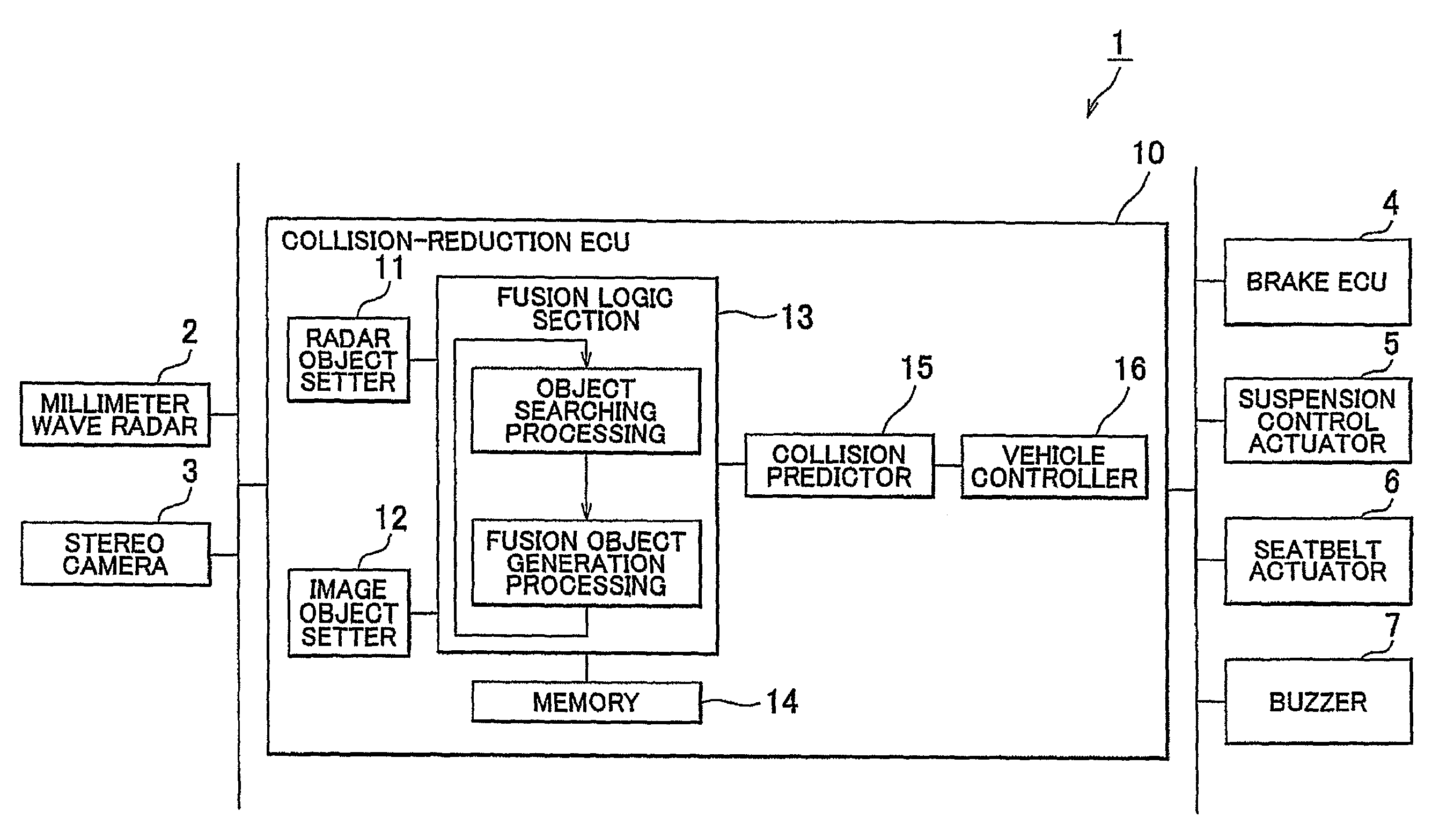
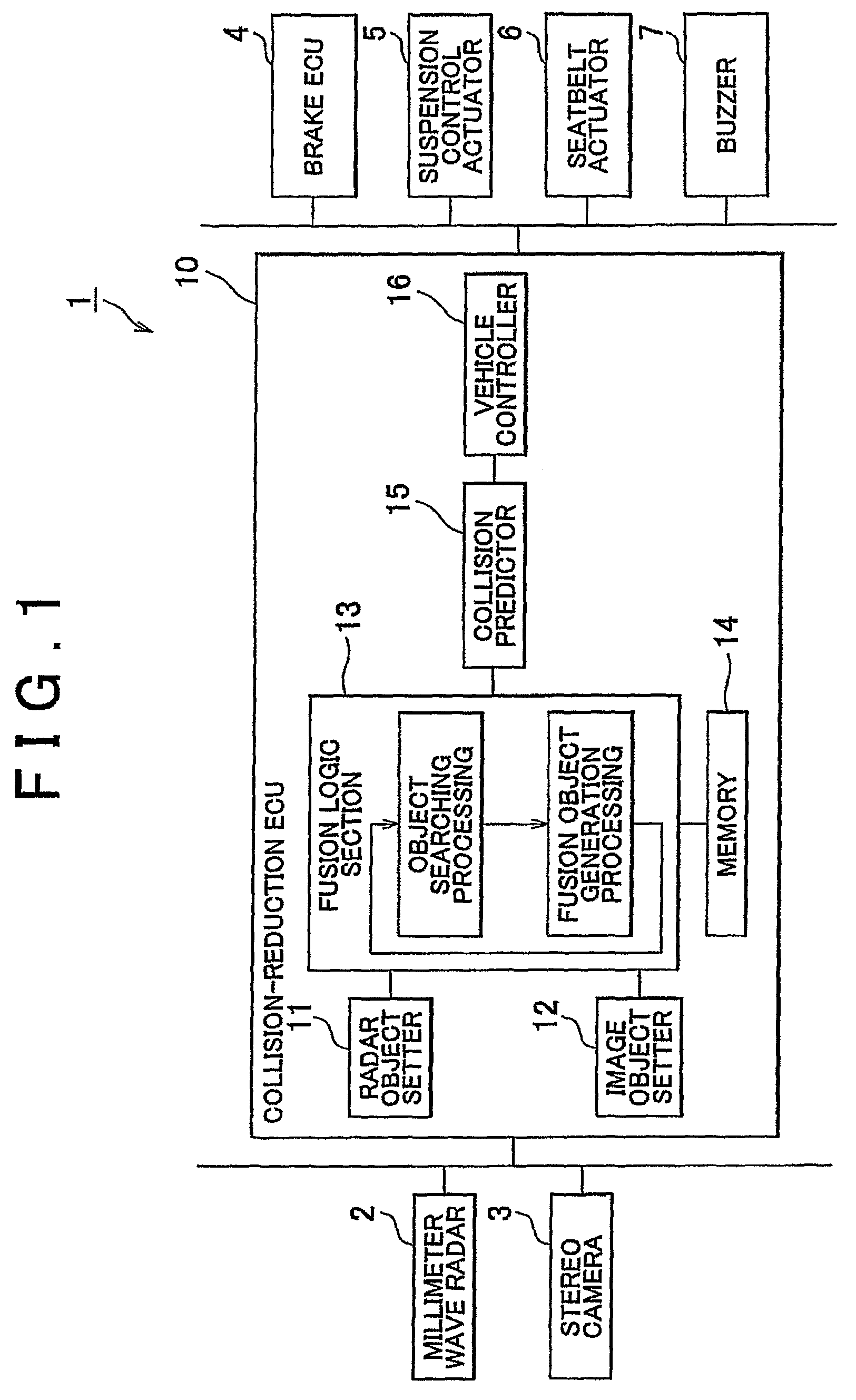
[0023]An example embodiment of an object detection apparatus according to the present invention is described below, with references made to the drawings. The embodiment is an example of application of an object detection apparatus of the present invention to a collision-reduction apparatus mounted on board a vehicle (“host vehicle”). The collision-reduction apparatus of this embodiment detects a vehicle in front of the host vehicle (“lead vehicle”) as the detection target and performs various controls to prevent or reduce collisions with the leading vehicle. Specifically, the collision-reduction apparatus of this embodiment has two sensors, a millimeter wave radar and a stereo camera, that detect the lead vehicle by comparing the object detected by the millimeter wave radar and the object detected by the stereo camera.

[0024]The collision-reduction apparatus 1 according to the embodiment of the present invention will be described with reference to FIG. 1 to FIG. 8. FIG. 1 shows the c...


PUM


Abstract

An object detection apparatus includes a radar that detects the position of an object; an imaging device that detects the position and size of an object; a fusion processing device that fuses the object detected by the radar device and the object detected by the imaging device as the same object, when the detection results of the radar device and the imaging device satisfy a prescribed fusion condition, to generate a fusion object having position information and size information. A provisional fusion object is generated if the detection result from the imaging device does not satisfy the fusion condition with respect to the detection result from the radar.

Description

BACKGROUND OF THE INVENTION[0001]1. Field of the Invention[0002]The present invention relates to an object detecting apparatus and method for detecting an object that combines the detection results of a radar means and an imaging means to detect an object.[0003]2. Description of the Related Art[0004]Driving support apparatuses such as collision-reduction apparatuses, adaptive cruise control apparatuses, and car-following apparatuses have been developed in recent years. In these driving support apparatuses, detection of a vehicle moving in front of the host vehicle is important. To improve detection accuracy, some object detection apparatuses have a radar means such as a millimeter wave radar and an imaging means such as a stereo camera. In an object detection apparatus having a radar means and an imaging means, the position (distance) of an object is detected by the radar means, and the size of the object is detected by the imaging means (refer to, for example, Japanese Patent Appli...

Claims


Application Information

Patent Timeline
Patent Type & Authority Patents(United States)
IPC IPC(8): G01S13/86G01S13/93G01S13/931G01S17/86G01S17/931
CPCG01S13/931G01S17/023G01S17/936G01S13/867G01S2013/9346G01S2013/9375G01S2013/9321G01S2013/9325G01S2013/93185G01S2013/93271G01S17/86G01S17/931
Inventor TSUCHIDA, JUNTOKORO, SETSUO
Owner TOYOTA JIDOSHA KK
Learn More