Operation method of nitride-based flash memory and method of reducing coupling interference

a technology of nitride-based flash memory and coupling interference, which is applied in the direction of static storage, digital storage, instruments, etc., can solve the problems of nitride-based memory structure similar coupling interference problems, vt shift threshold, and coupling interference issue of nitride-based memory cells, so as to reduce the coupling interference of nitride-based flash memory

Active Publication Date: 2010-11-02
MACRONIX INT CO LTD
View PDF17 Cites 4 Cited by
  • Summary
  • Abstract
  • Description
  • Claims
  • Application Information

AI Technical Summary

Benefits of technology

[0012]The present invention is directed to an operation method for a nitride-based flash memory and a method for reducing the coupling interference of the nitride-based flash memory, by performing an interference reduction operation (IRO) before the programming operation step. Through bias arrangement of the memory cell, charges are mainly injected into the charge trapping or storage layer above the junction regions of the memory cell, which can reduce the coupling interference of the nitride-based flash memory.
[0022]In the operation method of the present invention, by performing the interference reduction operation to the memory cell before the common programming operation reading operation, charges are injected into the storage layer mainly above the junction regions of the selected memory cell, thereby reducing the coupling interference. Hence, the threshold voltage shift caused by coupling interferences can be mitigated and wider operation windows are provided for the reading operation of the flash memory.

Problems solved by technology

As the floating gate based memory cell is continuingly scaled down and the distance between each two word-lines becomes too close, the coupling interference issues occur and result in a threshold voltage shift (Vt shift), which is one major problem faced in the industry.
However, it is found that the nitride-based memory structure has similar coupling interference issues.
From the experiment results, when scaling down the size of the memory cell, if the distance between each two adjacent word lines is too close, the coupling interference issue of the nitride-based memory cell arises.

Method used


Image

  • Operation method of nitride-based flash memory and method of reducing coupling interference
  • Operation method of nitride-based flash memory and method of reducing coupling interference
  • Operation method of nitride-based flash memory and method of reducing coupling interference

Examples


Embodiment Construction

[0034]Reference will now be made in detail to the present preferred embodiments of the invention, examples of which are illustrated in the accompanying drawings. Wherever possible, the same reference numbers are used in the drawings and the description to refer to the same or like parts.

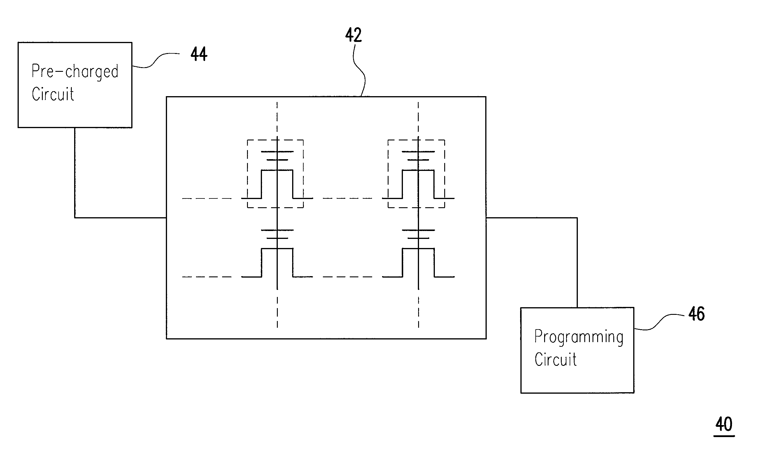
[0035]FIG. 4A is a schematic circuit diagram showing a non-volatile memory of the present invention. The non-volatile memory 40 includes a plurality of memory cells 42, either arranged in arrays or rows, a pre-charged circuit 44 and a programming circuit. The memory cell 42 generally includes at least a gate, a source region and a drain region in a substrate. An example of the detailed structure of the memory cell will be discussed in the following sections. However, the memory cell of this invention is not limited to the structure described herein, and possible modifications should be encompassed within the scope of the present invention. The pre-charged circuit 44 can apply a gate voltage VG to the...


PUM


Abstract

A method for operating a nitride-based flash memory is provided. The operation method includes pre-performing an interference reduction operation (IRO) before the routine programming operating step. Through bias arrangement of the target memory cell, charges are injected into the charge trapping layer mainly above the junction regions of the memory cell before programming so as to reset the influences caused by coupling interference issues. The operation method of this present invention not only reduces coupling interference but also afford a wider operation window.

Description

CROSS-REFERENCE TO RELATED APPLICATION[0001]This application claims the benefit of U.S. provisional application No. 61 / 020,370, filed on Jan. 10, 2008. The entirety of the above-mentioned patent application is hereby incorporated by reference herein and made a part of this specification.BACKGROUND OF THE INVENTION[0002]1. Field of the Invention[0003]The present invention relates to an operation method for a non-volatile memory structure; in particular, to an operation method for a nitride-based flash memory and a method for reducing coupling interference of a nitride-based flash memory.[0004]2. Description of Related Art[0005]In general, the non-volatile memory cell is comprised of a stacked gate, made of doped polysilicon and consisting of a floating gate and a control gate. A dielectric layer is disposed between the floating gate and the control gate, while a tunnel oxide layer is located between the floating gate and the substrate. The floating gate is disposed between the substr...

Claims


Application Information

Patent Timeline
Patent Type & Authority Patents(United States)
IPC IPC(8): G11C16/04
CPCG11C16/0466G11C16/10
Inventor WU, GUAN-WEIYANG, I-CHENCHANG, YAO-WEN
Owner MACRONIX INT CO LTD
Why Eureka
Try Eureka