Method for fault detection in an actuator

a technology of actuator and fault detection, applied in the direction of program control, instruments, testing/monitoring control systems, etc., can solve problems such as faults in actuators and/or sensors

Inactive Publication Date: 2010-11-02
ZF FRIEDRICHSHAFEN AG
View PDF14 Cites 5 Cited by
  • Summary
  • Abstract
  • Description
  • Claims
  • Application Information

AI Technical Summary

Benefits of technology

[0011]The advantage of this method is that the actuator movement indicated by the sensor and the actuator movement of the model are determined only over a defined time interval, so that a drifting separation of the measured and calculated actuator positions is prevented. This time interval is chosen to be not too large and thus covers about 10 to 20 calculation cycles. By summation of the movements typically over 10 to 20 calculation cycles the error occurring is limited to 10 to 20 times the error in one calculation cycle. This maximum error is taken into account in the comparison of the sensor and model position changes, whereby a fault in the actuator and / or the sensor for determining the actuator position is recognized with certainty. Thus, it is no longer necessary to feed back the measured actuator position to the modeling unit.

Problems solved by technology

If the measured and calculated actuator movements differ substantially, it can be concluded that there is a fault in the actuator and / or the sensor.

Method used


Image

  • Method for fault detection in an actuator
  • Method for fault detection in an actuator

Examples


Embodiment Construction

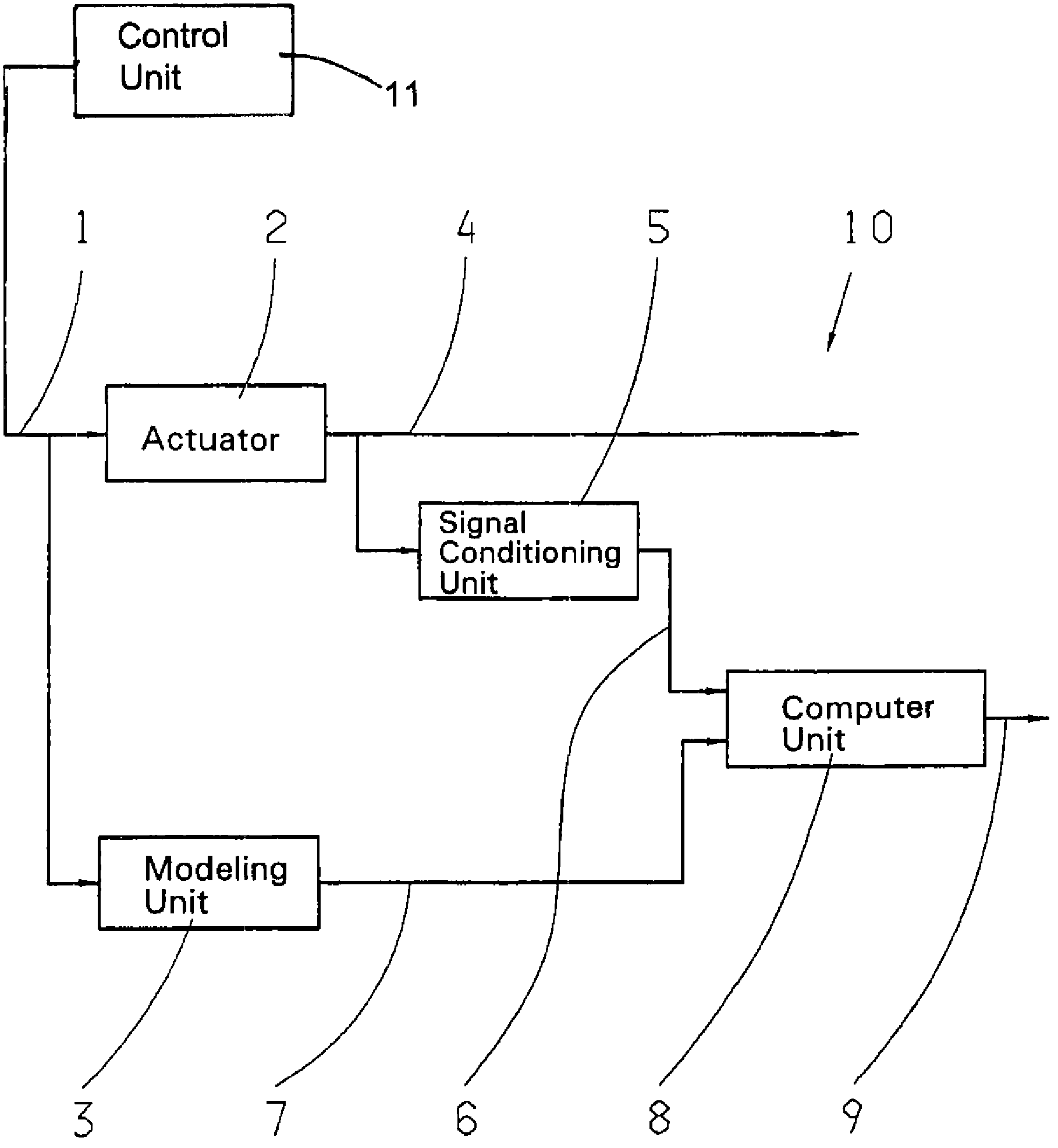
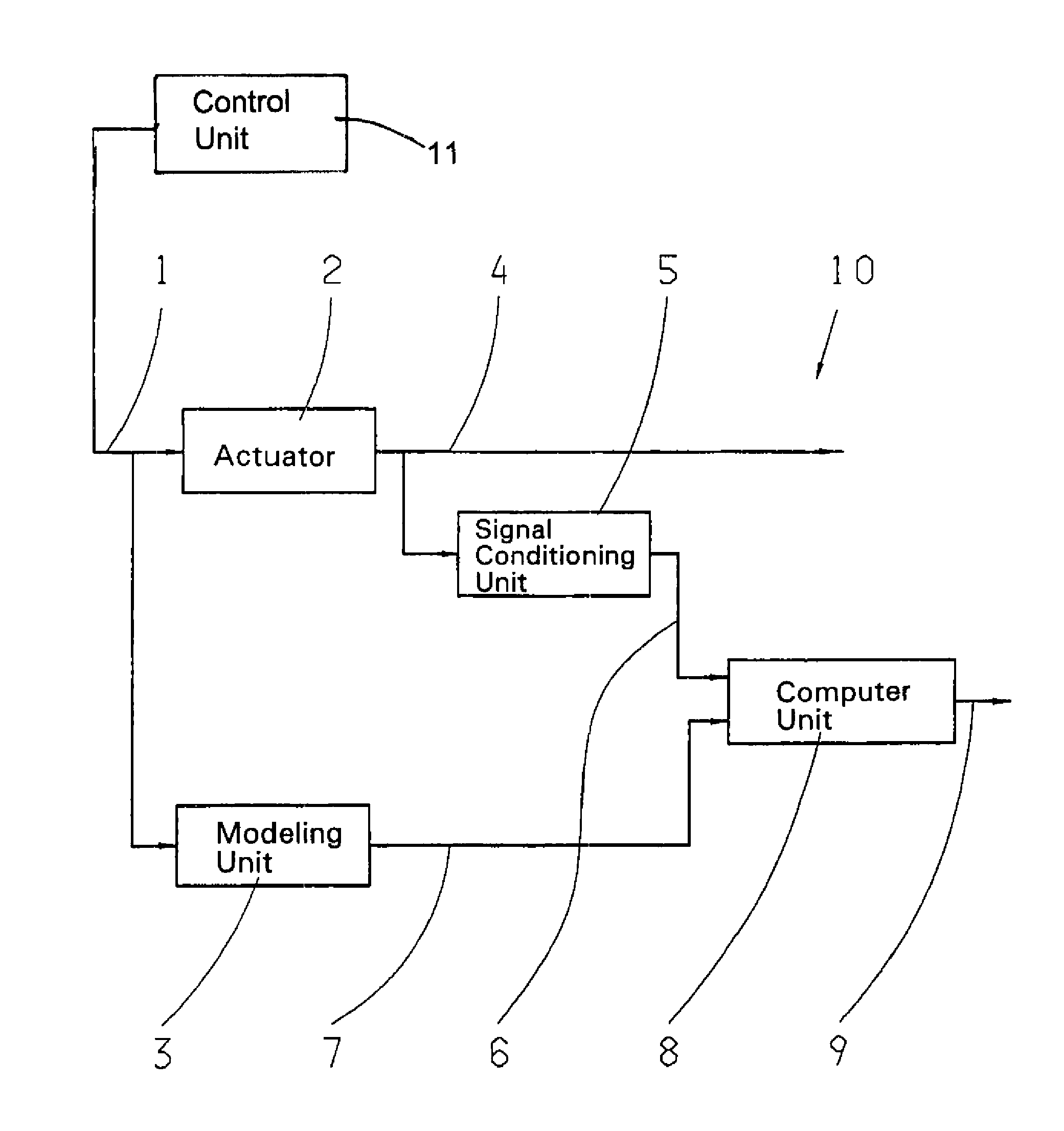
[0014]In the sole FIGURE, the block diagram 10 comprises an actuator 2, a modeling unit 3, a signal conditioning unit 5 and a computer unit 8. From a control unit 11, for example that of an automatic variable-speed transmission, a control value 1, appropriate for actuating the actuator 2, is sent both to the actuator 2 and to the modeling unit 3. As a function of the control value 1 applied, at an output of the actuator 2, a corresponding electric signal is produced by a sensor. This signal, which represents the measured actuator position 4, is sent to the signal conditioning unit 5. In the signal conditioning unit 5, the position change of the actuator, i.e., the actuator movement, is derived from the position signal of the sensor. At the output of the signal conditioning unit 5, the measured actuator movement 6 is now available. The control value 1 is also sent to the modeling unit 3. As a function of the control value 1 supplied, in the modeling unit 3, an expected actuator movem...


PUM


Abstract

A method for detecting fault in an actuator. By transmitting a control value, which is generated by a control unit, to an input of the actuator a signal for the measured actuator position is produced at the output of the actuator. The signal for the measured actuator position is sent to an input of a signal conditioning unit which determines from it a measure of actuator movement. The control value is also transmitted to an input of a modeling unit, which calculates from it an expected measure of actuator movement. These movements are sent to a computer unit, which produces a corresponding status signal for the functionality of the actuator and for the functionality of the sensor for determining the actuator position.

Description

[0001]This application is a national stage completion of PCT / EP2007 / 051679 filed Feb. 21, 2007, which claims priority from German Application Serial No. 10 2006 011 807.3 filed Mar. 15, 2006.FIELD OF THE INVENTION[0002]The invention concerns a method for fault detection in an actuator.BACKGROUND OF THE INVENTION[0003]In connection with automatic or automated variable-speed transmissions or clutches, it is known to derive a measurement magnitude by way of sensors, which indicates the position of an actuator. But since a sensor for detecting the position of an actuator may be defective, the actuator position indicated by the sensor is not unconditionally reliable. Thus, it is very advisable, in connection with the safety monitoring of automatic or automated change-speed transmissions, to check the actuator position.[0004]From DE 101 37 597 A1, a method for fault diagnosis in a clutch actuator is known. In this method, a control value is applied to an input of the clutch actuator. As a...

Claims


Application Information

Patent Timeline
Patent Type & Authority Patents(United States)
IPC IPC(8): G06F11/00G06F19/00F16H61/12
CPCF16D48/06F16H61/12G05B23/0243F16D2500/3026F16D2500/501F16D2500/5108F16D2500/70605F16D2500/7082F16H61/32F16H2061/1208G05B2219/24083F16H2061/1284F16H2061/1288
Inventor SCHNEIDER, FLORIANMAIR, ROLANDAPFELBACHER, BERNDJAGER, THOMAS
Owner ZF FRIEDRICHSHAFEN AG
Why Eureka
Try Eureka