Motor and disk drive using the same

a technology of motor and disk drive, which is applied in the direction of mechanical equipment, record information storage, instruments, etc., can solve the problems of increasing the demand for price reduction, unstable rotation of the rotor, and disk coming into contact with the magnetic head, so as to reduce the thickness of the motor, prevent the deterioration of the parallelism and reduce the inclination of the thrust yok

Active Publication Date: 2010-11-09
NIDEC CORP
View PDF19 Cites 23 Cited by
  • Summary
  • Abstract
  • Description
  • Claims
  • Application Information

AI Technical Summary

Benefits of technology

[0010]Since the bent portion extends downward from at least one of the inner periphery and the outer periphery of the substantially flat portion and the protruding portion extends downward from the bent portion, the thrust yoke can be made thin and the axial gap between the rotor and the thrust yoke can be reduced. Further, the thickness of the motor can be reduced.
[0011]Moreover, the area of contact between an upper surface of a base and the thrust yoke is reduced in the motor of the preferred embodiments of the present invention. Thus, it is possible to prevent deterioration of parallelism of the thrust yoke relative to the base in a circumferential direction and a radial direction, which deterioration comes from the contact between the base and the thrust yoke. That is, it is possible to reduce inclination of the thrust yoke relative to the base in the circumferential and radial directions. As a result, the axial gap between the thrust yoke and the rotor magnet can be made uniform in the circumferential direction. Accordingly, it is possible to reduce vibration caused by the inclination of the thrust yoke as well as noise due to the vibration in the rotor.

Problems solved by technology

If the yoke is attached obliquely relative to the rotor magnet, the magnetic attraction is uneven in the circumferential direction of the rotor magnet, thus making rotation of the rotor unstable.
Therefore, instable rotation of the rotor may cause the disk to come into contact with the magnetic head.
In addition, the recent price decline on disk drives has intensified demands for price reduction for motors to be mounted to the disk drives.

Method used


Image

  • Motor and disk drive using the same
  • Motor and disk drive using the same
  • Motor and disk drive using the same

Examples


first preferred embodiment

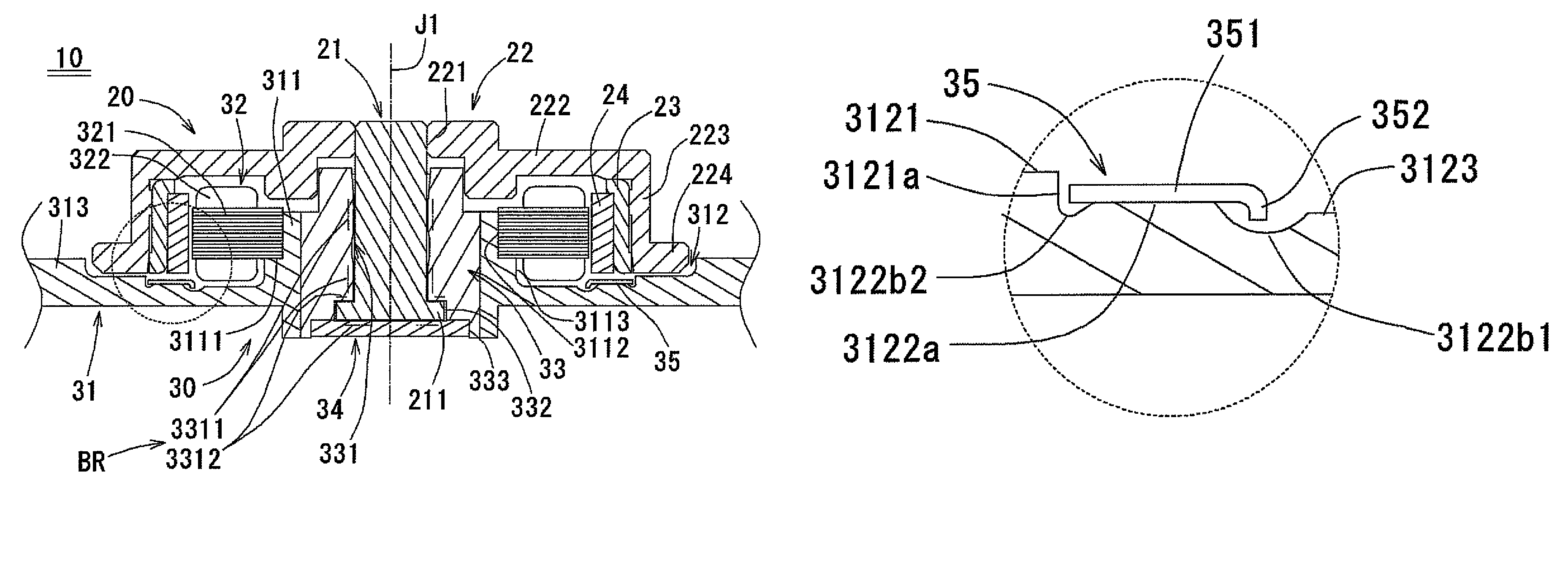
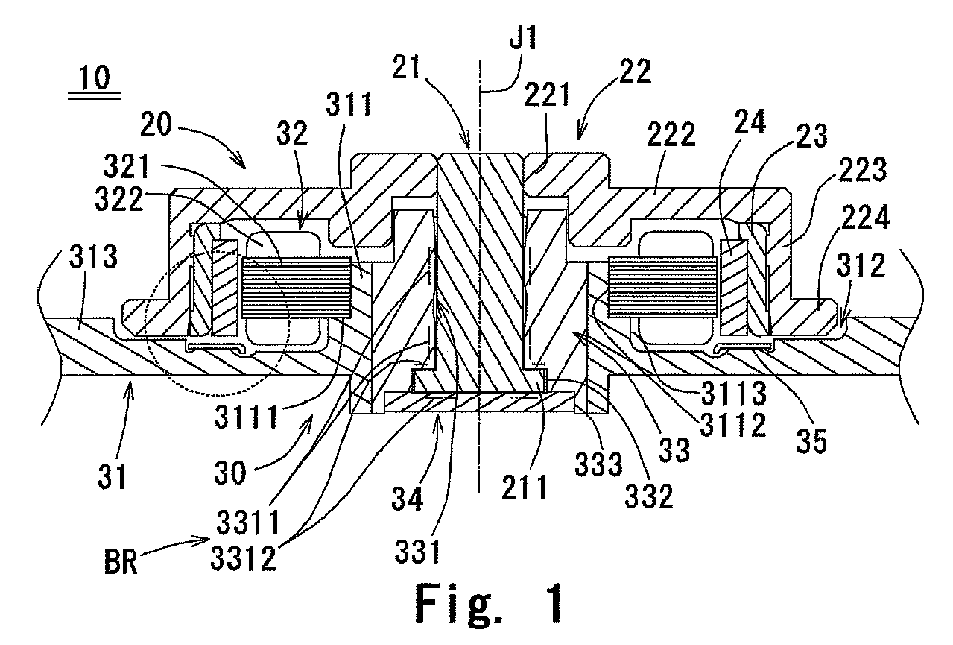
[0027]A motor according to a first preferred embodiment of the present invention is described referring to FIG. 1. FIG. 1 is a cross-sectional view of the motor of the first preferred embodiment, taken along a center axis J1 thereof.

[0028]Referring to FIG. 1, a motor 10 includes a rotor 20, a stationary unit 30, and a bearing unit BR. The rotor 20 includes a rotor magnet 24 that rotates about the central axis J1. The bearing unit BR supports the rotor 20. The stationary unit 30 includes a stator 32 that is arranged to oppose the rotor magnet 24 in a radial direction to generate a magnetic field, and a base 31 arranged to hold the stator 32.

[0029]The rotor 20 includes a shaft 21, a rotor hub 22, and a rotor yoke 23 in addition to the rotor magnet 24. The shaft 21 is arranged coaxially with the central axis J1 and rotates about the central axis J1. The rotor hub 22 is fixed on the upper portion of the shaft 21 and has a disk mount portion 224 for allowing a disk-shaped storage medium ...

second preferred embodiment

[0084]A motor of a second preferred embodiment of the present invention is now described referring to FIGS. 9 and 10. FIG. 9 is a cross-sectional view of the motor of this preferred embodiment, taken along a plane containing a center axis J1 thereof. FIG. 10 is an enlarged view of a portion of the motor of FIG. 9. The motor of this preferred embodiment includes a rotor 120 having a rotor magnet 124, a stationary unit 130, and a bearing unit BRa which supports the rotor 120 to be rotatable relative to the stationary unit 130

[0085]The stationary unit 130 includes a stator 132 and a base 131 arranged to hold the stator 132. The stator 132 has a stator core 321 and coil windings 322 arranged around the stator core 321.

[0086]The rotor 120 includes a shaft 121 arranged coaxially with the center axis J1, a rotor hub 122, and the rotor magnet 124. The rotor hub 122 has a cover portion 1222, a cylindrical portion 1223 extending downward from the outer periphery of the cover portion 1222, and...


PUM

PropertyMeasurementUnit
adhesiveaaaaaaaaaa
forceaaaaaaaaaa
magneticaaaaaaaaaa

Abstract

A thrust yoke is fixed into a second recessed portion of a base with adhesive. The second recessed portion has a first surface to be in contact with the bottom surface of the thrust yoke, and a second surface axially opposing the bottom surface of the thrust yoke with a gap therebetween. The thrust yoke has a bent portion at its radial end. The bent portion is bent downward. The thrust yoke also has a protruding portion extending downward from the bent portion. The protruding portion axially opposes the second surface of the second recessed portion of the base with a gap therebetween.

Description

BACKGROUND OF THE INVENTION[0001]1. Field of the Invention[0002]The present invention relates to a motor for spinning a disk-shaped storage medium and to a disk drive mounted with the motor.[0003]2. Description of the Related Art[0004]An exemplary known motor is described in JP 2006194400 A and its counterpart U.S. patent publication No. US 2006 / 0158052 A1. In the motor, magnetic attraction between a rotor magnet and a yoke made of magnetic material exerts a force in the opposite direction to the direction in which the rotor floats. That is, the magnetic attraction generated between the rotor magnet and the yoke is a reaction force to the force that makes the rotor float.[0005]If the yoke is attached obliquely relative to the rotor magnet, the magnetic attraction is uneven in the circumferential direction of the rotor magnet, thus making rotation of the rotor unstable. Particularly, a spindle motor used for spinning a disk-shaped storage medium (hereinafter, simply referred to as a ...

Claims


Application Information

Patent Timeline
Patent Type & Authority Patents(United States)
IPC IPC(8): H02K5/24G11B19/20H02K7/00
CPCG11B19/2009H02K5/163H02K7/085H02K7/09
Inventor YONEDA, TOMOHIROHAMAKAWA, KEITAIWASE, TAKAYUKIFUJII, HIROMASATAMAOKA, TAKEHITO
Owner NIDEC CORP
Why Eureka
Try Eureka