
Electro-optical element including IMI coatings

a technology of electrochromic elements and coatings, applied in the field of electrochromic elements, can solve the problems of insufficient reflectivity, inability to effectively solve the myriad of problems, and no group had commercial success, so as to reduce the cost of manufacturing, and reduce the overall cost of electrochromic elements

Active Publication Date: 2010-11-09
GENTEX CORP
View PDF179 Cites 184 Cited by
  • Summary
  • Abstract
  • Description
  • Claims
  • Application Information

AI Technical Summary

Benefits of technology

The present invention is an electrochromic element that includes a first substrate and a second substrate with a transparent electrode layer covering at least a portion of the substrates. The electrochromic element has a light transmittance that is variable upon the application of an electric field. The invention also includes a method for manufacturing the electrochromic element. The technical effects of the invention include reducing the overall cost of the electrochromic element without sacrificing optical and physical characteristics, providing a robust manufacturing process, and allowing tailored construction to achieve particular optical and physical properties.

Problems solved by technology

Although this concept was described as early as 1966, no group had commercial success because of the exacting criteria demanded from a workable auto-dimming mirror incorporating a third surface reflector.
Although a third surface reflector is discussed therein, the materials listed as being useful as a third surface reflector suffer from the deficiencies of not having sufficient reflectivity for use as an inside mirror, and / or not being stable when in contact with a solution-phase electrochromic medium containing at least one solution-phase electrochromic material.
While the adaptation of a reflective third surface electrochromic device has assisted in solving many problems, numerous deficiencies within these elements still exist.
While previous approaches have focused on indium tin oxide layers, these attempts have not effectively solved the myriad of problems noted above.
Specifically, several issues support the development of transparent conductor alternatives to indium-tin oxide.
Large electrochromic cells are particularly sensitive to sheet resistance, while high sheet resistance conductors lead to significant potential drops across the conductor surfaces.

Method used


Image

  • Electro-optical element including IMI coatings
  • Electro-optical element including IMI coatings
  • Electro-optical element including IMI coatings

Examples


Embodiment Construction

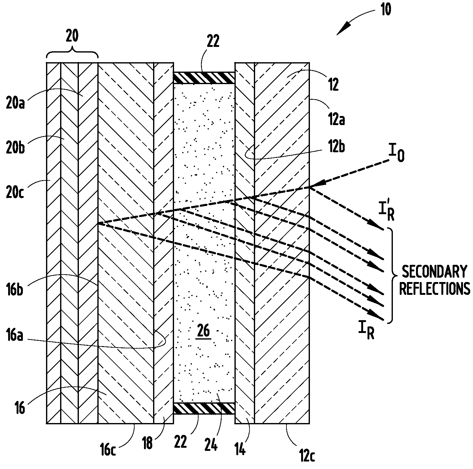
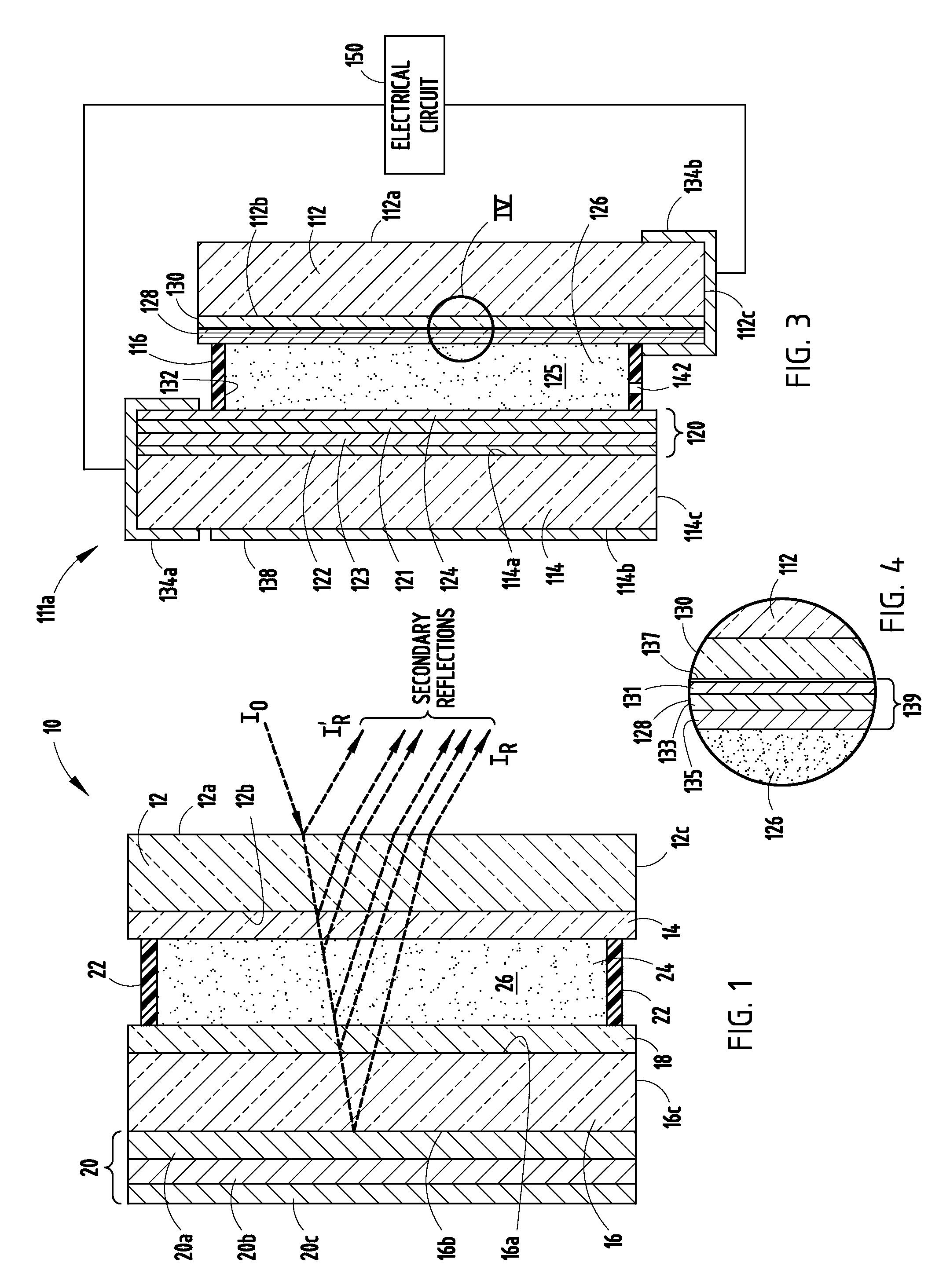
[0034]For purposes of description herein, the terms “upper,”“lower,”“right,”“left,”“rear,”“front,”“vertical,”“horizontal,” and derivatives thereof shall relate to the invention as oriented in FIGS. 1 and 3. However, it is to be understood that the invention may assume various alternative orientations and step sequences, except where expressly specified to the contrary. It is also to be understood that the specific devices and processes illustrated in the attached drawings, and described in the following specification are exemplary embodiments of the inventive concepts defined in the appended claims. Hence, specific dimensions and other physical characteristics relating to the embodiments disclosed herein are not to be considered as limiting, unless the claims expressly state otherwise.

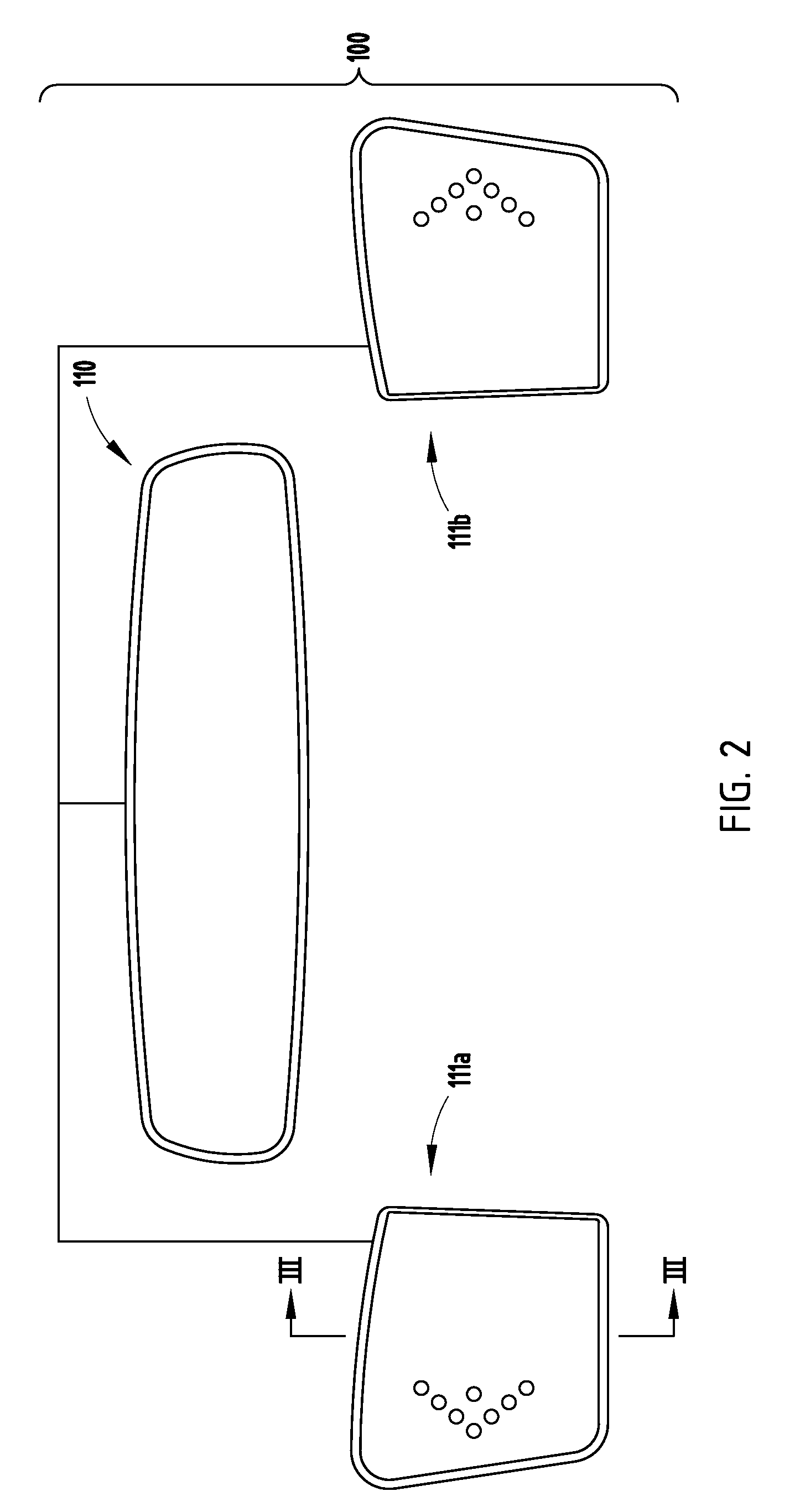
[0035]FIG. 2 shows a front elevational view schematically illustrating a vehicle mirror system 100 that includes an inside mirror assembly 110 and two outside rearview mirror assemblies 111a and 111b f...


PUM

PropertyMeasurementUnit
color rendering indexaaaaaaaaaa

Abstract

An electrochromic element comprises a first substrate having a first surface and a second surface opposite the first surface, a second substrate in spaced-apart relationship to the first substrate and having a third surface facing the second surface and a fourth surface opposite the third surface, and an electrochromic medium located between the first and second substrates, wherein the electrochromic medium has a light transmittance that is variable upon application of an electric field thereto. The electrochromic element further comprises a transparent electrode layer covering at least a portion of at least a select one of the first surface, the second surface, the third surface, and the fourth surface, wherein the transparent electrode layer comprises an insulator / metal / insulator stack. The materials utilized to construct the insulator / metal / insulator stack are selected to optimize optical and physical properties of the electrochromic element such as reflectivity, color, electrical switch stability, and environmental durability.

Description

CROSS REFERENCE TO RELATED APPLICATION[0001]This application claims the benefit of U.S. Provisional Application No. 60 / 779,369, filed Mar. 3, 2006, entitled IMPROVED COATINGS AND REARVIEW ELEMENTS INCORPORATING THE COATINGS, and U.S. Provisional Application No. 60 / 810,921, filed Jun. 5, 2006, entitled ELECTROCHROMIC REARVIEW MIRROR ASSEMBLY INCORPORATING A DISPLAY / SIGNAL LIGHT, both of which are hereby incorporated herein by reference in their entirety.BACKGROUND OF THE INVENTION[0002]This invention relates to electrochromic elements as utilized within rearview mirror assemblies for motor vehicles, as well as within window assemblies, and more particularly, to improved electrochromic elements for use within such assemblies. More particularly, the present invention relates to electrochromic elements that comprise transparent electrode layers that include insulator / metal / insulator stacks.[0003]Heretofore, various rearview mirrors for motor vehicles have been proposed which change from...

Claims


Application Information

Patent Timeline
Patent Type & Authority Patents(United States)
IPC IPC(8): G02F1/15G02F1/155G02F1/153
CPCB60R1/088G02F1/153G02F1/155G02F1/157E06B9/24G02F1/13439G02F1/161G02F1/163G02F2201/48G02F2203/02G02F1/136204C03C17/3644C03C2217/944
Inventor NEUMAN, GEORGE A.LUTEN, HENRY A.ANDERSON, JOHN S.FORGETTE, JEFFREY A.VANDER ZWAAG, SCOTT W.
Owner GENTEX CORP
Learn More