Lock apparatus for a glove box of a vehicle

a technology for locking apparatus and glove box, which is applied in the direction of keyhole guards, roofs, instruments, etc., can solve the problems of poor operation of the knob from the driver seat, degrading the appearance large door thickness of the glove box, so as to achieve wide housing space in the glove box and simplify the structure of the glove box

Inactive Publication Date: 2010-11-16
KOJIMA PRESS IND CO LTD
View PDF34 Cites 26 Cited by
  • Summary
  • Abstract
  • Description
  • Claims
  • Application Information

AI Technical Summary

Benefits of technology

[0061]According to the lock apparatus according to item (1) above, the following technical advantages can be obtained in all Embodiments 1-5 of the present invention:(a) Since the knob is disposed at a portion of the instrument panel closer to the driver seat than the center of the glove box in the right and left direction of the glove box, an operability of the knob by a driver from the driver seat is good.
[0097]According to the lock apparatus according to item (29) above, since each of the pair of lock portions includes the rotational member supported by the lock casing so as to be linearly slidable in opposite directions and having an inclined groove, and the lock engaging piece having a pin engaging the inclined groove of the rotational member and moving in a direction to and away from the glove box when the rotational member is moved linearly in opposite directions relative to the lock casing, a linear motion of the wire can be easily exchanged to a motion of the lock engaging piece in the direction to and away from the glove box.

Problems solved by technology

(a) Since the knob is located at the center of the glove box, the knob is located relatively far from a driver seat. As a result, an operability of the knob from the driver seat is poor.
(b) Since the knob is of a rotation type, a recess for inserting a finger may be required to be provided beneath and at a rear of the knob, which degrades the appearance of the glove box. Further, a door thickness of the glove box is rather large, which reduces the housing space of the glove box.
(c) If the knob provided to the glove box is changed from one of the rotation type to one of a push type in order to decrease the drawback of item (b) above, an open direction of the glove box becomes reverse to the push direction of the knob, which lowers the opening operability of the glove box.
(d) If the knob is offset to one of the ends of the glove box in the right and left directions of the glove box in order to decrease the drawback of item (a) above, when the knob is operated or the glove box is closed, a load is imposed on the one end of the glove box thereby causing a deformation of the glove box. As a result, a step and a clearance are generated between a surface of at least the one end of the glove box in the right and left direction of the glove box and a surface of the instrument panel, which degrades the appearance of the glove box.
(e) In order to decrease the drawback of item (d) above, if a lock portion is provided at each end of the glove box in the right and left direction of the glove box and the knob is offset to one of the ends of the glove box in the right and left directions to lock and unlock the lock portions, due to a torsion generated in an operation force transmitting member extending between the right and left lock portions, the right and left lock portions do not operate synchronously. As a result, one side locking, where only one lock portion is locked, and the other lock portion is not locked is likely to take place, which will increase a deformation of the glove box. If a torsional rigidity of the operation force transmitting member is increased, a cross section of the operation force transmitting member is large, so that the housing space of the glove box is small.

Method used


Image

  • Lock apparatus for a glove box of a vehicle
  • Lock apparatus for a glove box of a vehicle
  • Lock apparatus for a glove box of a vehicle

Examples


embodiment 1

FIGS. 1, 6 and 7

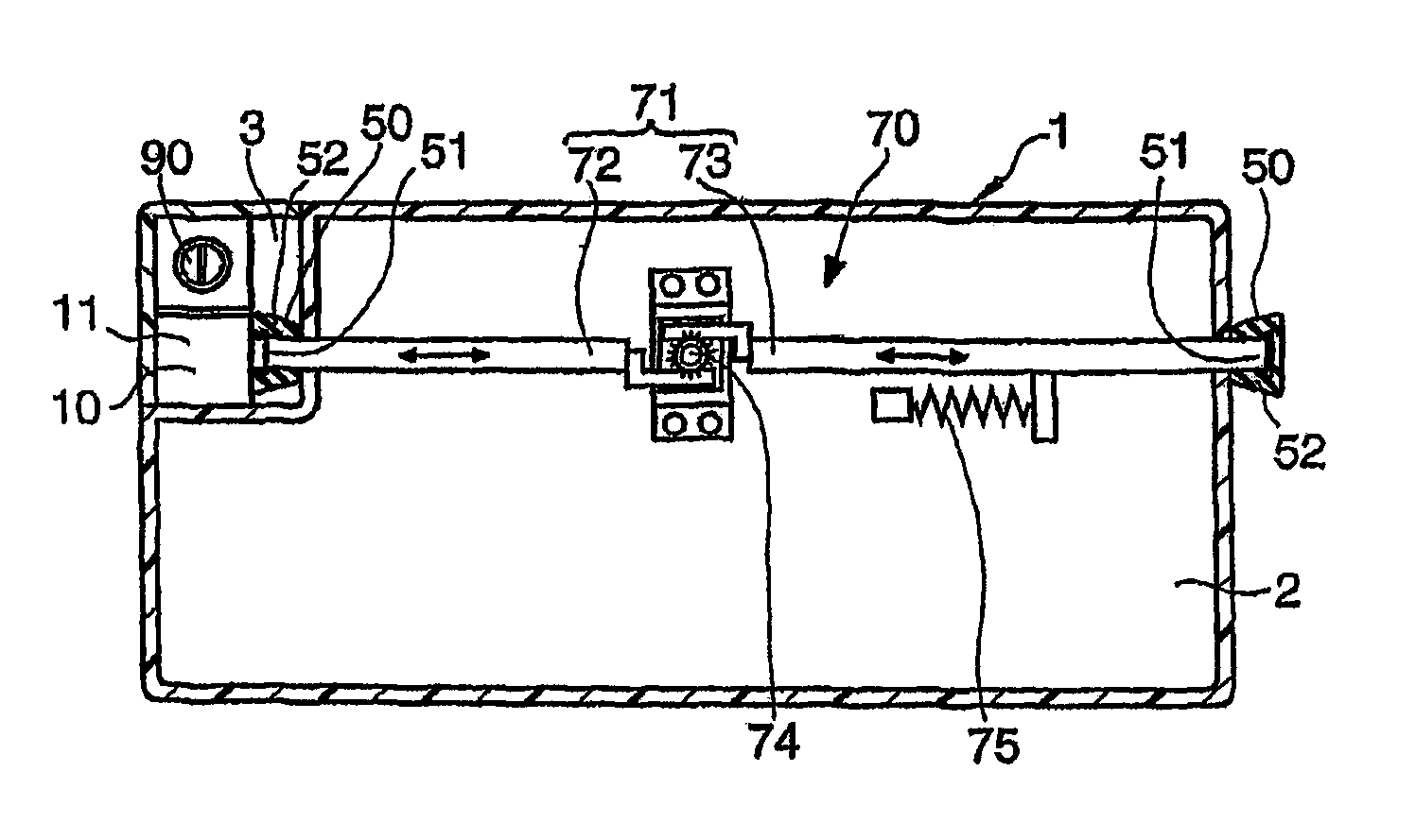
[0138]In Embodiment 1 of the present invention, as illustrated in FIGS. 1, 6 and 7, the operating portion 10 includes an operating piece 12 movable linearly and reciprocally in a plane perpendicular to a movement of the knob 11. The transmitting portion 70 is adapted to transmit a motion of the operating piece 12 of the operating portion 10 to each of the pair of lock portions 50 synchronously relative to each other.

[0139]The operating portion 10 is supported by the instrument panel 3. The exchanging portion 13 of the operating portion 10 includes an inclined plane so that when pushing the knob 11, the knob 11 moves the operating piece 12 toward glove box 2 via the exchanging portion 13, pushing the operating piece 12 in opposition to a biasing force by a pulling spring 14.

[0140]The transmitting portion 70 is supported by the glove box 2 between the instrument panel 3 and the glove box 2.

[0141]The transmitting portion 70 includes: a first rod 72 supported by the glov...

embodiment 2

FIGS. 2, and 8-10

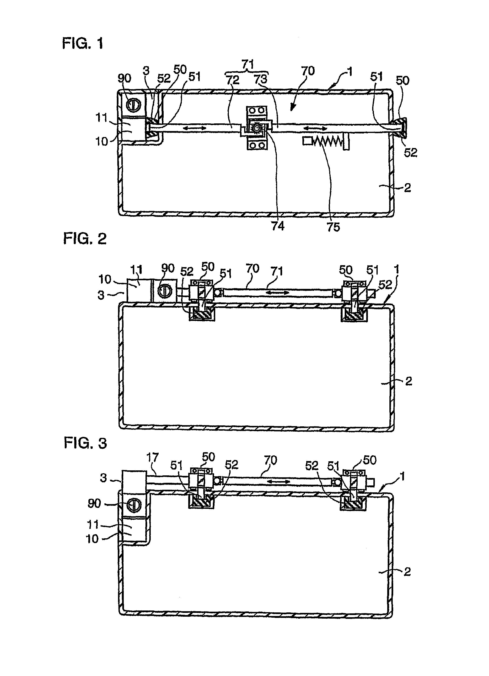
[0150]In Embodiment 2 of the present invention, as illustrated in FIGS. 2, and 8-10, the operating portion 10 includes an operating piece 12 movable linearly and reciprocally in a plane perpendicular to a movement of the knob 11. The transmitting portion 70 is adapted to transmit a motion of the operating piece 12 of the operating portion 10 to each of the pair of lock portions 50 synchronously relative to each other.

[0151]The operating portion 10 is supported by the instrument panel 3. The exchanging portion 13 of the operating portion 10 includes an inclined plane so that when pushing the knob 11, the knob 11 pulls the operating piece 12 via the exchanging portion 13, pulling an intermediate member 54 of the lock male portion 51 of the lock portion 50 in opposition to a biasing force of the pushing spring 15. The spring 15 always biases the transmitting member 71 of the transmitting portion 70 in a direction pushing the transmitting member.

[0152]The transmitting p...

embodiment 3

FIGS. 3, and 8-1

[0165]In Embodiment 3 of the present invention, as illustrated in FIGS. 3, 11, and 8-10 (FIGS. 8-10 are applicable to not only Embodiment 2 but also Embodiment 3), the transmitting portion 70 is adapted to transmit a motion of the operating piece 12 of the operating portion 10 to each of the pair of lock portions 50 synchronously relative to each other.

[0166]The operating piece 12 of the operating portion 10 includes a pivotally supported member 16 and a transmitting rod 17 for transmitting a motion of the pivotally supported member 16 to the intermediate member 54 of the lock portion 50.

[0167]The pivotally supported member 16 is pivotally supported by the instrument panel 3 so that one end of the pivotally supported member 16 reciprocally and arcuately moves in the right and left direction of the glove box 2. The transmitting rod 17 connects the one end of the pivotally supported member 16 with the intermediate member 54 of the lock male portion 51 of the lock porti...


PUM


Abstract

A lock apparatus for locking a glove box that is rotatably coupled to an instrument panel of a vehicle. The lock apparatus includes an operating portion with a push-type knob, a pair of lock portions, and a transmitting portion with a transmitting member. The operating portion is located closer to a driver seat than a right and left center of the glove box in a right and left direction of a vehicle. The operating portion is coupled to the instrument panel between the instrument panel and the glove box. Each of the lock portions is located at each of right and left end portions of the glove box. The transmitting portion transmits a motion of the operating portion to each of the pair of lock portions using tension and / or compression of the transmitting member.

Description

[0001]This is a 371 national phase application of PCT / JP2005 / 000812 filed 18 Jan. 2005, the content of which is incorporated herein by reference.TECHNICAL FIELD[0002]The present invention relates to a lock apparatus. More specifically, the present invention relates to a lock apparatus for locking an opening and closing motion of a glove box of a vehicle.BACKGROUND[0003]A lock apparatus for a glove box which is coupled to an instrument panel of a vehicle so as to be able to be open and closed is disclosed in Japanese Patent Publication 2003-13647 and Japanese Patent Publication 2003-13655.[0004]Japanese Patent Publication 2003-13647 discloses that a knob (an operating handle) is located at a center of a glove box, that the knob is provided not to an instrument panel but to the glove box, and that the knob is of a rotation type (not of a push type).[0005]Japanese Patent Publication 2003-13655 also discloses that a knob (an operating handle) is located at a center of a glove box, that ...

Claims


Application Information

Patent Timeline
Patent Type & Authority Patents(United States)
IPC IPC(8): B65D55/14
CPCE05B83/30E05B79/20E05C9/00E05C9/041E05C9/1841Y10S292/37Y10T70/5558Y10T70/5761Y10T70/5889Y10T292/0843Y10T292/0845
Inventor KOZUKA, AKIHIKOSAEKI, TOSHI
Owner KOJIMA PRESS IND CO LTD
Why Eureka
Try Eureka