Device and method for through-cutting of an extruded ice mass

Inactive Publication Date: 2010-11-16
TETRA LAVAL HLDG & FINANCE SA
19 Cites 5 Cited by

AI-Extracted Technical Summary

Problems solved by technology

But, this through-cutting however is not suitable for through-cutting of ice cream containing solid ingredients, such as nuts, berries or the like as the wire does not have a cutting edge, and the ingredients cannot be through-cut by through-melting.
This make...

Method used

[0024]As it is indicated in FIG. 2, the second stroke length of the second knife 5 is about half of the stroke length of the first knife 4. Furthermore, the edges 4′, 5′ of the knives 4, 5 are preferably V-shaped as shown in FIG. 3 so that ...

Benefits of technology

[0012]Thus, the device preferably comprises means for control of the movements of the knives, insuring guidance of the first knife in a first transverse stroke which consists in a complete through-cutting of the ice mass, and that the second knife, in a simultaneous movement, is guided partly through the ice mass in an oppositely directed stroke of which the direction of movement is opposite the direction of movement of the first stroke. In that the ice mass continuously is extruded with an essentially constant flow velocity out of the nozzle, the thickness of the cut-off pieces will be uniform and the distance on the conveyer will be essentially identical if the device is activated with a constant frequency. This frequency can preferably be adjusted with respect to the actual product, which is to be produced by the machine.
[0013]In a preferred embodiment of the invention, the second stroke length of the second knife is half of the first stroke length. Furthermore, the edges of the knives are preferably V-shaped, so that the knives can easily slide against each other without risk of mutual collision.
[0014]The first and the second knives are, in the preferred embodiment, arranged on parallel guides of a frame in the means of control with opposing inactive positions arranged on each side of a path of the ice mass which is extr...

Abstract

A device for through-cutting of an extruded ice mass, which has a first knife which is reciprocably arranged in a transverse first plane immediately after the outlet of the nozzle and arranged with a first length of stroke and a second knife which is reciprocably arranged in a plane which is parallel to the first plane and which is arranged immediately below the first knife with respect to the flow direction out of the nozzle, the second knife is arranged with a second stroke length which is smaller than the first stroke length, and a control for producing simultaneous reciprocation of the first and the second knife. Hereby, a shearing is achieved which is more precise and commonly applicable for manufacturing of ice cream portions by an automated production of ice cream products.

Application Domain

Technology Topic

Image

  • Device and method for through-cutting of an extruded ice mass
  • Device and method for through-cutting of an extruded ice mass
  • Device and method for through-cutting of an extruded ice mass

Examples

  • Experimental program(1)

Example

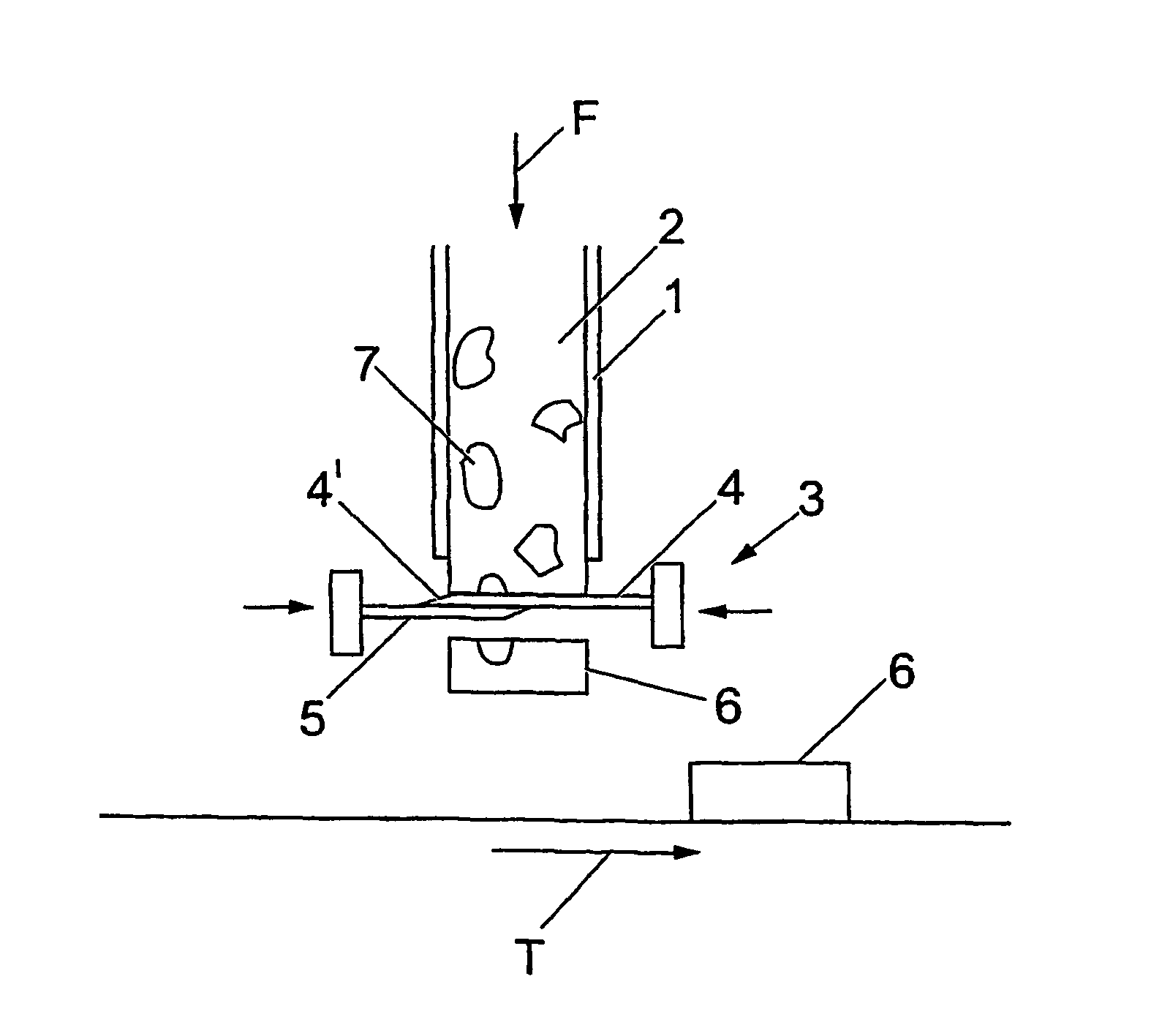
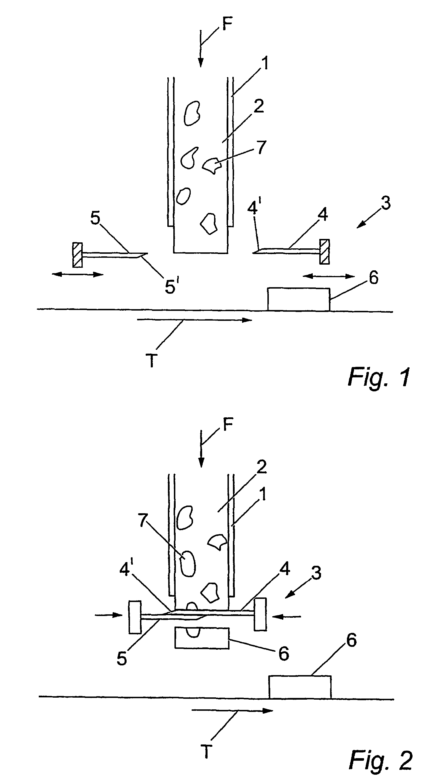
[0022]FIGS. 1 and 2 show a device for through-cutting by a shearing of an extruded ice mass according to a preferred embodiment of the invention. An ice cream mass 2 is shaped by extrusion out of a nozzle 1, which comprises a pipe section with a predetermined cross-sectional shape. The ice cream 2, having a high viscosity, is forced out of the nozzle 1 with an essentially constant flow velocity F. Immediately after the outlet of the nozzle 1, a through-cutting device 3 is arranged which comprises an upper first knife 4 and a lower second knife 5. The two knives are arranged in parallel so they can be moved in separate and planes, which preferably are orthogonal with respect to the flow direction of the ice mass, however in such a way that the cutting planes of the knives are essentially the same. In FIG. 1, the knives 4, 5 are shown in their inactive positions, and in FIG. 2, they are shown in their projected positions. As shown in the figures, the ice cream 2 may contain solid ingredients 7, such as berries or nuts, for example, which is desirable in relation to producing variants of ice cream products.
[0023]As it is apparent from FIG. 2, the first knife 4 is guided in a first transverse stroke which consists in a complete through-cutting of the ice mass 2, and the second knife 5 is guided in a simultaneous movement partly through the ice mass in an oppositely directed stroke of which the direction of movement is opposite the direction of movement in the first stroke. Together, the knives 4, 5 are, in this way, performing a sort of through-shearing of the extruding ice cream from the nozzle 1. By extruding the ice mass 2 continuously out of the nozzle with an essentially constant flow velocity F, the thickness of the cut-off pieces 6 will be uniform and the distance on the conveyer T will be essentially identical if the device 3 is activated with a constant frequency. This frequency can preferably be adjusted with respect to the actual product, which is to be produced by the machine.
[0024]As it is indicated in FIG. 2, the second stroke length of the second knife 5 is about half of the stroke length of the first knife 4. Furthermore, the edges 4′, 5′ of the knives 4, 5 are preferably V-shaped as shown in FIG. 3 so that the knives 4, 5 can easily slide against each other without risk of mutual collision. Thereby, there is no risk as well that the knives are sliding askew in the guiding frame 9 as a result of uneven resistance in the ice cream, for example.
[0025]The first knife and the second knife are, in the preferred embodiment, arranged in parallel guides on a frame 9 of the means of control with opposing inactive positions arranged on each side of the ice mass 2 which is extruded from the nozzle 1. As shown in FIG. 3, there may, in connection with the nozzle 1, be means for insertion of an ice cream lolly stick 8 in the ice mass 2, e.g., through an opening 13 in the nozzle 1 immediately before the outlet (see, FIGS. 4 and 5).
[0026]As shown in FIG. 3, the first and the second knives 4, 5 are eccentrically connected to rotor means 10 which by coupling means 11 are attached to rotating drive means 12 whereby a continuous rotational movement from the drive means 12 is transferred to the rotor means 10 and transformed into a translational movement of the knives 4, 5. The coupling means 11 could, in the example shown, be a pneumatically activatable coupling which is attached to control means (not shown), which comprises an electric or pneumatic control for attaching the coupling 11 for performing a through-cutting in dependency on the flow velocity F of the ice mass 2 out from the nozzle 1.
[0027]In FIG. 4, the device in a preferred embodiment is shown in perspective. As it appears from FIG. 4, the cutting device 3 is arranged below the nozzle 1. As it appears from FIG. 4, the upper knife 4 and the lower knife 5 are slidably arranged on side guides of the frame 9. Below is arranged the conveyer T onto which the cut-off products are received and transported onward for further processing. As it is seen, the nozzle 1 is equipped with a slot 13 through which an ice cream lolly stick can be hacked into the ice cream in the nozzle immediately before the outlet. This mounting of an ice cream lolly stick in the ice cream is naturally synchronized with the flow velocity F and the frequency of the through-cutting by the device 3, so that it is ensured that an ice cream lolly stick 8 is mounted in each cut-off ice product 6.
[0028]In FIG. 5, the device 3 for through-shearing the extruded ice mass 2 is shown in perspective, as seen from below. As it appears from this figure, the upper knife 4 can be provided with a V-shaped knife-edge 4′ and the lower knife 5 is provided with a straight knife-edge 5′.
[0029]The rotor means 10, working as a “crank”, pulls the knives 4, 5 forward and backward and the electromagnet brake/coupling 11 controls when the knives 4, 5 start and stop. The rotor means moves a full cycle (360°). The coupling means receives a signal with a given frequency for when a through-shearing is to begin, and depending on the time interval between these signals, the thickness of the ice slice which is cut is controlled. Preferably, a signal provider (not shown) is also arranged recording when a knife 4, 5 is in a start or stop position. This signal is used for activation of the coupling means for braking/engaging the knives 4, 5. As shown in FIG. 5, a gear mechanism 14 is arranged in connection with the lower knife 5, which causes the knife 5 to almost stop while the upper knife 4, which is connected to the gear mechanism 15, cuts the ice slice 6. The gear mechanisms 14, 15 are constructed in such a way that they return the knives 4, 5 simultaneously.
[0030]Above, the invention is described in relation to an example of an embodiment. It is, however, in connection to the invention, realized that equivalent embodiments such as, e.g., other types of mechanical guides and controls of the movements of the knives could be provided without deviating from the fundamental idea of the invention as specified in the appended patent claims.

PUM

PropertyMeasurementUnit
Length
Mass
Velocity
tensileMPa
Particle sizePa
strength10

Description & Claims & Application Information

We can also present the details of the Description, Claims and Application information to help users get a comprehensive understanding of the technical details of the patent, such as background art, summary of invention, brief description of drawings, description of embodiments, and other original content. On the other hand, users can also determine the specific scope of protection of the technology through the list of claims; as well as understand the changes in the life cycle of the technology with the presentation of the patent timeline. Login to view more.

Similar technology patents

Liquid crystal display panel

Owner:HONG FU JIN PRECISION IND (SHENZHEN) CO LTD +1

Classification and recommendation of technical efficacy words

  • Uniform thickness
  • Easily slide

Module retention latch assembly

InactiveUS20050083670A1Easily slideEngagement/disengagement of coupling partsIncorrect coupling preventionRetaining ringMoving between two positions
Owner:MOLEX INC

Desk-top steaming apparatus

InactiveUS20060070532A1Easily slideAir-treating devicesOven air-treatment devicesWater pipeWater supply
Owner:CHANG RONG KUAN

Repair using plastic as the sliding mechanism for laterally sliding doors/windows

InactiveUS7010830B2Easily slideEasily and cost effectively instal and replaceCurtain suspension devicesCastorsHigh-density polyethyleneSliding glass door
Owner:SIROCHMAN JOSEPH WILLIAM

Eyeglass frame system where lenses can move from one frame to another

ActiveUS20170227786A1More experienceEasily slideSpectales/gogglesLens assembliesCamera lensFastener
Owner:KLIX FRAMES USA LLC
Why Eureka
Try Eureka