Apparatus and method for coupling a disconnectable stabilizer bar

a stabilizer bar and disconnection technology, applied in the direction of couplings, torsion springs, interlocking clutches, etc., can solve the problems of the vehicle body accelerating to roll, affecting the ability of the driver to control the vehicle, and causing the vehicle to roll at a relatively higher ra

Active Publication Date: 2010-11-16
AMERICAN AXLE & MFG
View PDF49 Cites 26 Cited by
  • Summary
  • Abstract
  • Description
  • Claims
  • Application Information

AI Technical Summary

Benefits of technology

[0003]Traditional vehicle suspension systems include resilient devices, such as coil springs and leaf springs, to flexibly support a portion of a vehicle. These devices enable all of the vehicle wheels to maintain contract with the ground when traversing uneven terrain. Segregating the vehicle into unsprung and sprung portions in this manner is also useful for preventing severe impulsive forces from being transmitted to the vehicle occupants.
[0005]In tuning the ride and handling of a vehicle, it is often desirable to soften or lower the spring rate of the suspension's springs to provide a softer, less harsh ride. One of the main drawbacks associated with this approach is that a suspension system having springs with a relatively low spring rate permits the vehicle body to roll at a relatively higher rate. Accordingly, it would seem that the combination of springs with a very low spring rate and a relatively stiff stabilizer bar would optimize both the ride and handling of the vehicle.

Problems solved by technology

It is known that when vehicle travels around a corner, centrifugal forces acting on the vehicle tend to cause the sprung portion of the vehicle to roll.
In severe instances, the effects of roll can cause instability and impede the ability of the driver to control the vehicle.
One of the main drawbacks associated with this approach is that a suspension system having springs with a relatively low spring rate permits the vehicle body to roll at a relatively higher rate.
This “cross-talk” between the vehicle wheels can be undesirable.
Another drawback of stabilizer bars is that their torsional stiffness inhibits the free travel of the vehicle wheels.
Modern materials and design techniques have substantially reduced the weight of the vehicle wheels and mounting structures to such an extent that the weight of a wheel and its mounting structure is typically insufficient to cause the stabilizer bar to rotate.
While this problem is rarely, if ever, noticed on the relatively flat surfaces of modern roads, it can become apparent when the vehicle is operated over un-even terrain.
While such configurations are suitable for their intended purpose, they are nonetheless susceptible to improvement.

Method used


Image

  • Apparatus and method for coupling a disconnectable stabilizer bar
  • Apparatus and method for coupling a disconnectable stabilizer bar
  • Apparatus and method for coupling a disconnectable stabilizer bar

Examples


Embodiment Construction

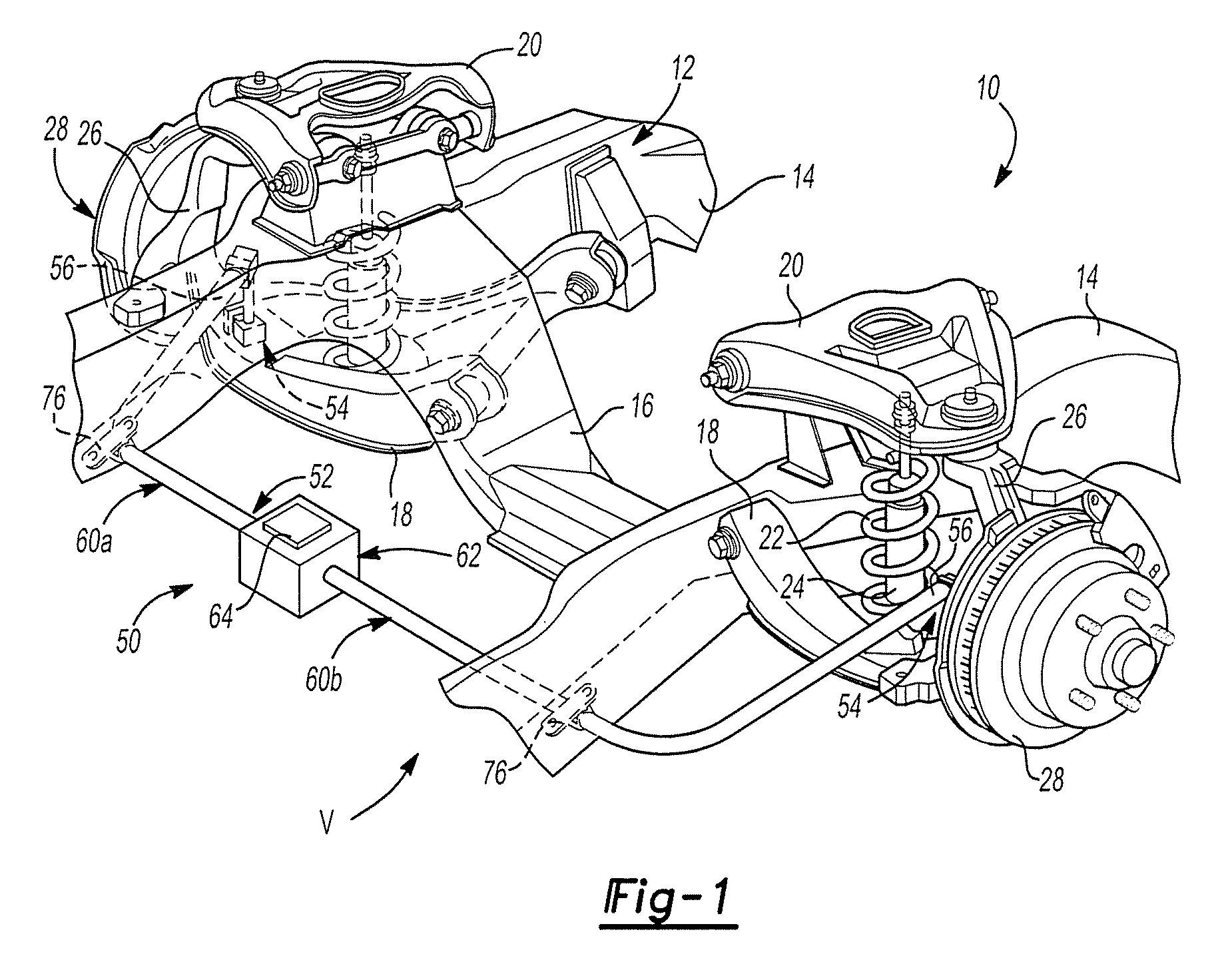
[0022]With reference to FIG. 1 of the drawings, an exemplary vehicle is shown and can include an independent front suspension system 10. The independent front wheel suspension can be of a type having suspension components at each wheel that are suspended from the vehicle frame structure 12. In the particular example provided, the frame structure 12 can include a pair of longitudinal side rails 14 and a crossbeam 16, but those of ordinary skill in the art will appreciate that the term “frame structure” need not refer to a frame as such, but could also refer to one or more regions of the vehicle body that act as an integrated frame structure. Those of ordinary skill in the art will appreciate that although a front suspension system is illustrated and described herein, the teachings of the present disclosure are also applicable to a rear suspension system.

[0023]At each wheel, the suspension system 10 can include a lower control arm 18 and an upper control arm 20. The lower and upper co...


PUM


Abstract

A vehicle stabilizer bar assembly having a pair of stabilizer bar members that are selectively uncoupled via a clutch. The clutch includes a moving element that can be selectively moved via an actuator to effect the uncoupling of the stabilizer bar members. The actuator is configured to apply a force to the moving element concentrically about the axis along which the moving element translates. The clutch is configured to transmit torque from one of the stabilizer bar members to the other stabilizer bar member concentrically about the axis. A method for operating a vehicle stabilizer bar assembly is also provided.

Description

RELATED APPLICATIONS[0001]This application claims the benefit of U.S. Provisional Patent Application No. 60 / 857,149 entitled “Apparatus And Method For Coupling A Disconnectable Stabilizer Bar” filed Nov. 6, 2006.INTRODUCTION[0002]The present invention generally relates to vehicle suspension systems and more particularly to an anti-roll suspension system having a pair of independently mounted stabilizer bar halves that can be selectively de-coupled from one another.[0003]Traditional vehicle suspension systems include resilient devices, such as coil springs and leaf springs, to flexibly support a portion of a vehicle. These devices enable all of the vehicle wheels to maintain contract with the ground when traversing uneven terrain. Segregating the vehicle into unsprung and sprung portions in this manner is also useful for preventing severe impulsive forces from being transmitted to the vehicle occupants.[0004]It is known that when vehicle travels around a corner, centrifugal forces ac...

Claims


Application Information

Patent Timeline
Patent Type & Authority Patents(United States)
IPC IPC(8): B60G17/015
CPCB60G3/20B60G17/0162B60G21/0556B60G21/106F16D27/118B60G2202/135B60G2202/42B60G2202/44B60G2204/419B60G2204/82B60G2204/83B60G2401/172B60G2600/08B60G2800/012F16D2300/18
Inventor PINKOS, ANDREW F.YORK, TODD M.GILMORE, CURT D.OLIVEIRA, GARY A.DANIELSEN, MARK A.
Owner AMERICAN AXLE & MFG
Why Eureka
Try Eureka