Rolling bearing apparatus

a technology of rolling bearings and rollers, which is applied in mechanical equipment, machines/engines, drip or splash lubrication, etc., can solve the problems of generating lubricating oil and unable to supply lubricating oil to a proper position, so as to reduce the frequency of maintenance work, reduce noise, and reduce the amount of discharged lubricating oil

Inactive Publication Date: 2010-11-16
JTEKT CORP
View PDF10 Cites 16 Cited by
  • Summary
  • Abstract
  • Description
  • Claims
  • Application Information

AI Technical Summary

Benefits of technology

[0004]An object of the invention is to provide a rolling bearing apparatus preventing a lubricating oil from leaking and preventing an oil drop from moving to an opposite direction, whereby the lubricating oil is securely supplied to a proper position even in a case of being used at a high speed rotation.
[0008]The lubricating oil discharge nozzle is, for example, positioned in a lowest portion of the rolling bearing, and is constituted by a main body extending in a horizontal direction and a discharge portion bent approximately perpendicular to the main body, and a discharge portion is directed to a flow direction of the air (the rotating direction). In this case, the direction of the discharge portion is not limited to a horizontal direction (a parallel direction to the flow direction of the air), but may be inclined downward with respect to the main body. An angle α of the discharge portion in this case with respect to the horizontal direction is appropriately determined in a range which is equal to or more than 0 degree (including the parallel direction to the flow direction of the air) and less than 90 degree (not including the vertical direction to the flow direction of the air). In this case, it is preferable that an installed position of the lubricating oil discharge nozzle, that is, an installed position of the pump is set to a lower side of the tank, however, is not limited to the lowest portion of the rolling bearing. It is possible to prevent the lubricating oil from leaking and prevent the oil drop from moving in an opposite direction, by inclining the opening direction of the nozzle to the flow direction of the air generated due to rotation. It is preferable that a leading end portion of the nozzle is bent in the rotating direction, and it is preferable that the opening direction of the nozzle is perpendicular to the direction of the center axis of rotation.
[0015]The discharge amount of the lubricating oil by the pump is controlled by the drive portion. For example, very small amount of lubricating oil is discharged to the portion near the rolling elements or a raceway groove of the raceway member in a region in which the rotating speed of the rotating side raceway member is low, and in a region in which the rotating speed is high, a corresponding amount of lubricating oil thereto is discharged. As mentioned above, it is possible to continuously supply the lubricating oil to the rolling element rolling region of the rolling bearing in just proportion over a long term, and it is possible to contribute to a long-term stabilization of a rolling characteristic and an improvement of a service life.
[0017]The rolling bearing apparatus can be preferably used as a bearing for a spindle of a machine tool (particularly rotated at a high speed having a high rotating speed, for example, equal to or more than ten thousand) desired to supply a small amount of lubricating oil for the long term while reducing a frequency of a maintenance work. Since the lubrication of the rolling bearing apparatus can make a noise lower in comparison with the lubricating oil lubrication or the air lubrication used in the machine tool, and an amount of the discharged lubricating oil is reduced, an environmentally friendly structure is obtained. Further, since the lubrication of the rolling bearing apparatus can make a torque lower in comparison with a grease lubrication, and is suitable for a high-speed rotation, the rolling bearing apparatus can be used as a bearing apparatus of various apparatuses which cannot use the lubricating oil for the reason that a handling characteristic is inferior to the grease lubrication.
[0018]In accordance with the rolling bearing apparatus of the invention, since the opening direction of the nozzle is directed to a proper direction taking into consideration the rotating direction of the rolling bearing, it is possible to prevent the lubricating oil from leaking and prevent the oil drop from moving in the opposite direction, whereby even in a case where the apparatus is used under the high-speed rotation, it is possible to securely supply the lubricating oil to the proper position.

Problems solved by technology

This kind of rolling bearing apparatus is used in a machine tool or the like, however, in a case where it is used at a high speed rotation, there is a problem that a leak of the lubricating oil tends to be generated due to a negative pressure generated in a leading end portion of the nozzle, and there is further a problem that an oil drop once discharged from the nozzle moves to a root side of the nozzle and the lubricating oil cannot be supplied to a proper position.

Method used


Image

  • Rolling bearing apparatus
  • Rolling bearing apparatus
  • Rolling bearing apparatus

Examples


Embodiment Construction

[0026]A description will be given below of embodiments in accordance with the invention with reference to the accompanying drawings.

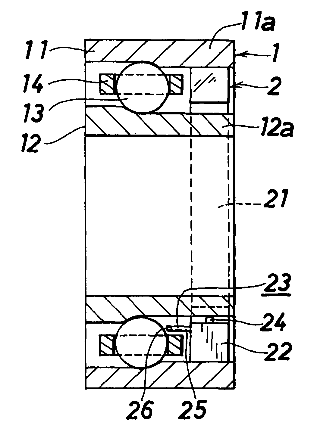
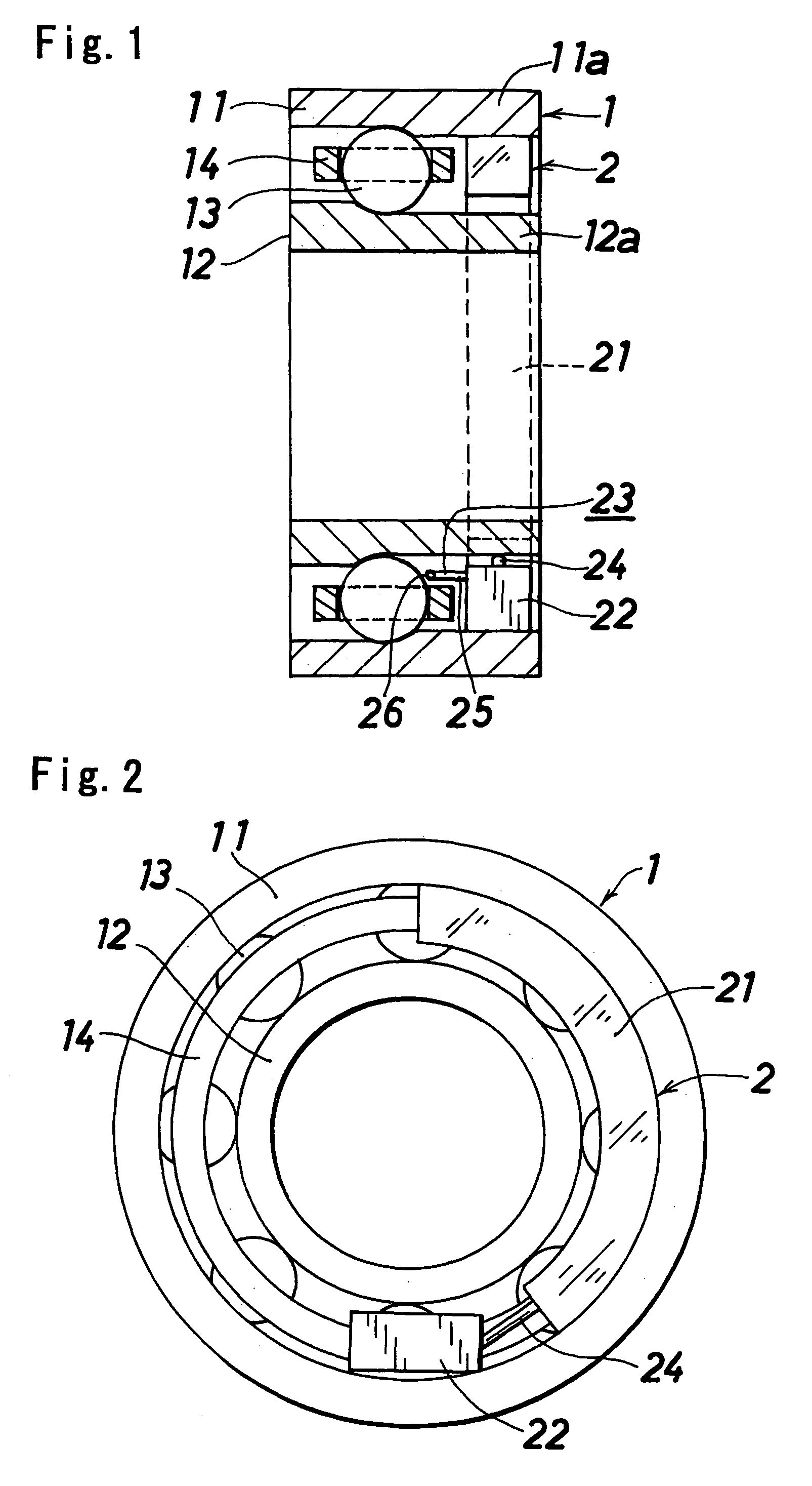
[0027]FIGS. 1 to 3 show a first embodiment of a rolling bearing apparatus in accordance with the invention. In the following description, upper and lower mean upper and lower in FIGS. 1 and 2, and the upper and the lower coincide with upper and lower at a time when the rolling bearing is attached.

[0028]The rolling bearing apparatus in accordance with the invention is constituted by a rolling bearing 1 and an oil supply unit 2.

[0029]The rolling bearing 1 corresponds to an inner ring rotating ball bearing, and is provided with an outer ring (a fixed side raceway member) 11, an inner ring (a rotating side raceway member) 12, a plurality of balls (rolling elements) 13 allowing both the rings 11 and 12 to relatively rotate, and a cage 14 holding a plurality of balls 13.

[0030]The oil supply unit 2 is provided with a tank 21 storing a lubricating oil, a pump 2...


PUM


Abstract

An oil supply unit provided in a rolling bearing apparatus has a lubricating oil discharge nozzle in which an opening is faced to a cage portion of the rolling bearing. An opening direction of the nozzle is inclined to a rotating direction with respect to a direction of a center axis of rotation.

Description

BACKGROUND OF THE INVENTION[0001]The invention relates to a rolling bearing apparatus in which a rolling bearing is provided with an oil supply unit supplying a small amount of lubricating oil.[0002]As the rolling bearing apparatus provided with the oil supply unit, in Japanese Unexamined Patent Publication No. 2004-108388, there is proposed one in which a fixed side raceway member of a rolling bearing is provided with an oil supply unit supplying a lubricating oil to rolling elements or a raceway surface of the raceway member as an occasion demands, and the oil supply unit is provided with a tank storing the lubricating oil, a micro pump sucking the lubricating oil within the tank so as to discharge, a nozzle arranged in a discharge port of the micro pump and having an opening facing to a portion near the rolling elements or the raceway surface of the raceway member, and a drive portion driving the micro pump.[0003]This kind of rolling bearing apparatus is used in a machine tool or...

Claims


Application Information

Patent Timeline
Patent Type & Authority Patents(United States)
IPC IPC(8): F16C19/00F01M11/02
CPCF16C33/6674F16C19/163F16C33/664
Inventor SUZUKI, KAZUYA
Owner JTEKT CORP
Why Eureka
Try Eureka