Compensation techniques for variations in image field data

a compensation technique and image field technology, applied in the field of video signal processing, can solve the problems of significantly non-uniform image of the scene, uneven light distribution, and unsuitability for most optical applications, and achieve the effect of low cost and not adversely affecting the performance of the video system

Inactive Publication Date: 2010-11-16
QUALCOMM INC
View PDF39 Cites 24 Cited by
  • Summary
  • Abstract
  • Description
  • Claims
  • Application Information

AI Technical Summary

Benefits of technology

[0006]The electronic signal processing techniques of the present invention allow compensation for lens shading and / or other similar phenomenon, such as sensor sensitivity variations and internal camera reflections, which superimpose a predictable optical variation onto the image across a multi-element photo-sensor. These techniques have particular application to digital cameras and other types of video devices but are not limited to such optical photo system applications. The techniques may be implemented at a low cost, require a minimum amount of memory, and operate at the same rate as the video data being modified is obtained from the photo-sensor, thereby not adversely affecting the performance of the video system. This is accomplished by applying correction factors in real time to the output signals of the photo-sensor in order to compensate for undesired intensity patterns across the photo-sensor that are complex as well as patterns that are regular in shape such as circular, elliptical or hyperbolic shaped patterns.
[0007]In an example of such compensation, the data of each pixel is corrected by an amount that is a function of the radius of the pixel from the optical center of the image or other light pattern (also referred to herein as the anchor point or center of gravity of the light pattern). The position of each pixel is first converted from a x-y coordinate position of the raster or other linear scanning pattern to a radial distance, and then that radial distance is used to generate the correction for the pixel from a small amount of correction information stored in a small memory. This avoids having to keep correction data for each pixel, and thus saves having to include a large memory to store such data. Use of circuits dedicated to carrying out these operations allows them to be performed at the same rate as the video data is outputted by the photo-sensor, without having to employ an extremely fast, expensive digital signal processor. In a particular application, the radial position of a pixel is calculated from the scan position by an adder circuit without the need for more complex circuitry to perform multiplication or division.
[0008]Each camera or optical system of some other device is calibrated, in one example, by imaging a scene of uniform intensity onto the photo-sensor, capturing data of a resulting intensity variation across the photo-sensor, characterizing the intensity variation according to a known geometric pattern and then storing a relatively few data points defining the geometric pattern, in order to minimize the amount of memory required to store correction data. A determination of correction values between the stored values are obtained during the image modification process by a form of interpolation. In order to avoid noticeable discontinuities in the image intensity, these few data points are preferably fit to a smooth curve that is chosen to match the intensity variation across the image that is to be corrected. In addition to correcting for lens shading, these techniques also correct for any intensity variations caused by the photo-sensor and / or its interaction with the incident image light.

Problems solved by technology

In the case of a lens alone, a simple lens used to view a scene with a uniform light intensity across it will typically produce an image of that scene having a significantly non-uniform light intensity.
Such a lens obviously is not suitable for most optical applications without this effect being corrected.
Shading effects of lenses that image object scenes onto the photo-sensor, non-uniform sensitivity of the photo-sensor to various colors of light striking it, and potentially other factors, cause an uneven distribution of light across the photo-sensor, and thus video signals from the sensor include data of the undesired intensity variation superimposed thereon.

Method used


Image

  • Compensation techniques for variations in image field data
  • Compensation techniques for variations in image field data
  • Compensation techniques for variations in image field data

Examples


Embodiment Construction

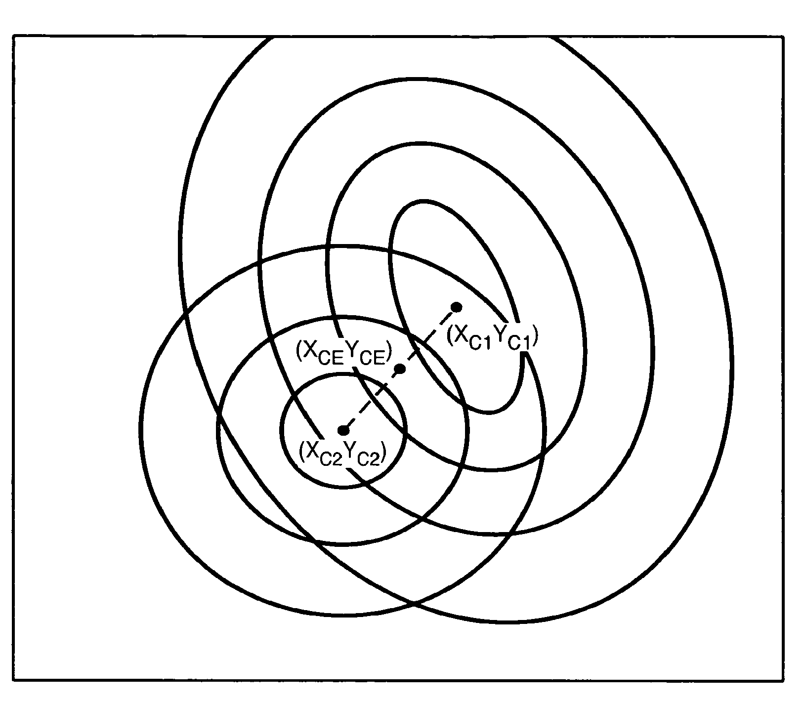
[0023]The superimposition of variations onto an image or other desired light pattern, due to the phenomena previously discussed, results in a variation of energy in each pixel of that image. These energy variations are not related to the captured image data itself. In order to compensate for this variation in energy across the photo-sensor, each pixel value could be combined, such as by multiplication, with a shading correction density factor. This factor is unique to each pixel in the image sensor according to the pixel's geographic location in the image sensor matrix. In the ideal case, a table of factors could be created during a calibration procedure that stores the required compensation factor for each pixel of the image in memory. This would allow the needed shading compensation to be effected by executing the following equation with a processing unit in the image capturing device:

PixelOut=PixelIn*F(X,Y)  (1)

Where,[0024]PixelOut=The output of the Image Shading Compensation mod...


PUM


Abstract

Techniques for modifying data of an image that can be implemented in a digital camera, video image capturing device and other optical systems are provided to correct for image shading variations appearing in data from a two-dimensional photo-sensor. These variations can be caused by imperfect lenses, non-uniform sensitivity across the photo-sensor, and internal reflections within a housing of the optical system, for example. In order to correct for these variations, a small amount of modification data is stored in a small memory within the camera or other optical system, preferably separate correction data for each primary color. The modification data is generated on the fly, at the same rate as the image data is being acquired, so that the modification takes place without slowing down data transfer from the image sensor.

Description

CROSS-REFERENCE TO RELATED APPLICATION[0001]This application is a Continuation of U.S. Ser. No. 10 / 749,669, filed Dec. 30, 2003, which is a Continuation-In-Part of U.S. Ser. No. 10 / 222,412, filed Aug. 16, 2002, and is related to U.S. Ser. No. 10 / 770,696, filed Feb. 2, 2004, which is a Continuation-In-Part of the '412 application, and U.S. Ser. No. 12 / 140,257, filed on Jun. 16, 2008, which is a Continuation of the '696 application, all four of which are incorporated herein by reference.FIELD OF THE INVENTION[0002]This invention relates generally to techniques of processing video signal data, and, more specifically, to processing video binary data to correct for variations across an imaged optical field such as, for example, to compensate for shading effects caused by lenses, sensor sensitivity variations and housing internal reflections in cameras and the like.BACKGROUND[0003]Image shading is a non-uniform light response across an image field. It can be attributed in an optical syste...

Claims


Application Information

Patent Timeline
Patent Type & Authority Patents(United States)
IPC IPC(8): H04N9/64H04N5/225G06T5/00G06T5/20H04N1/401H04N5/217H04N5/243H04N101/00
CPCG06T5/006H04N5/217H04N9/045H04N5/243H04N5/3572H04N5/2178H04N25/67H04N23/81H04N23/76H04N25/61H04N25/611
Inventor PINTO, VICTORGALIL, EREZ
Owner QUALCOMM INC
Why Eureka
Try Eureka