Gas-insulated electric power apparatus

a technology of electric power equipment and gas-insulated electric equipment, which is applied in the direction of gas-insulated substations, switchgear arrangements, substation/switching arrangement details, etc., can solve the problems increasing the cost, and increasing the total length of gas-insulated electric equipment in the horizontal direction. , to achieve the effect of increasing the installation space of gas-insulated electric equipment and pushing up the cos

Inactive Publication Date: 2010-11-16
MITSUBISHI ELECTRIC CORP
View PDF42 Cites 35 Cited by
  • Summary
  • Abstract
  • Description
  • Claims
  • Application Information

AI Technical Summary

Benefits of technology

[0012]As shown in FIG. 1 of the above-mentioned patent document 1, in the constitution in which the current transformer 4 is arranged on the breaker portion 1a, the electric power cable connection portion 2 is arranged on the horizontal side of the current transformer 4, and the voltage transformer 6 is arranged on the further horizontal side of the electric power cable connection portion 2, a total height of the gas-insulated electric apparatus becomes low compared to the case shown in FIG. 2 of the patent document 1 and hence, there hardly occurs case that the total height exceeds a height limit of an ordinary road, for example, 3.6 m whereby it is almost unnecessary to perform the extra work that the gas-insulated electric apparatus is once disassembled before transporting and the gas-insulated electric apparatus is assembled on a site again after transporting. However, a total length of the gas-insulated electric apparatus in the horizontal direction is elongated compared to the case shown in FIG. 2 of patent document 1 and hence, an installation space for the gas-insulated electric apparatus is increased. For example, when the gas-insulated electric apparatus is applied to an indoor power substation, there arises a drawback that a building becomes large-sized thus pushing up a cost.

Problems solved by technology

For example, when the gas-insulated electric apparatus is applied to an indoor power substation, there arises a drawback that a building becomes large-sized thus pushing up a cost.
However, with such a constitution, although a total height of the gas-insulated electric apparatus becomes further lower than a corresponding height of the gas-insulated electric apparatus shown in FIG. 1 of the patent document 1, there arises a drawback that a total length of the gas-insulated electric apparatus in the horizontal direction becomes further elongated compared with the case of FIG. 1 of the patent document 1.

Method used


Image

  • Gas-insulated electric power apparatus
  • Gas-insulated electric power apparatus
  • Gas-insulated electric power apparatus

Examples


embodiment 1

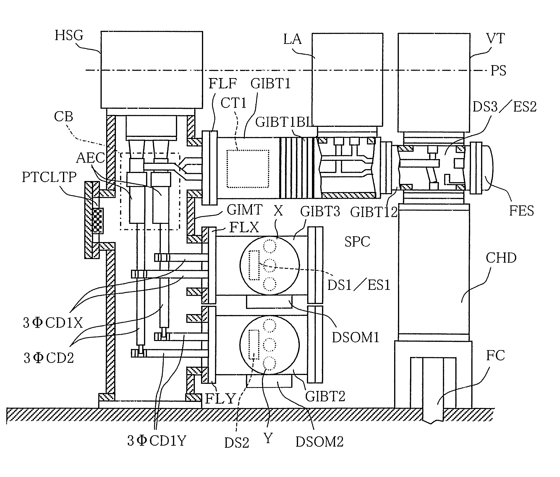
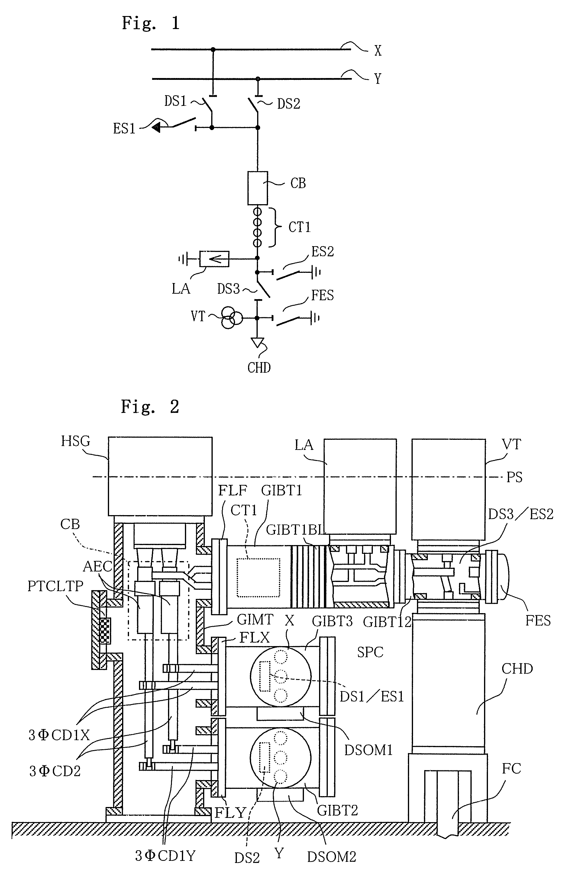
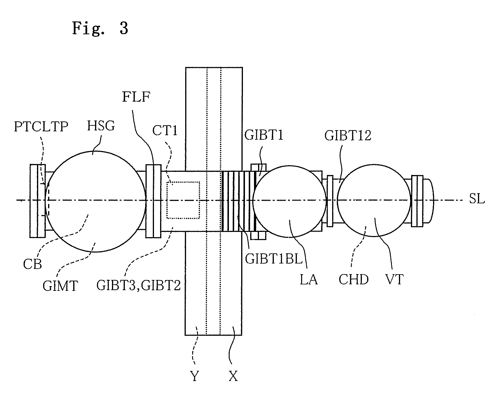
[0028]An embodiment 1 of the present invention is explained in conjunction with FIG. 1 to FIG. 3. FIG. 1 is a system view showing one example of an electricity supply system adopting a double-bus-line method. FIG. 2 is a side view with a part in cross section showing one example of a gas-insulated electric apparatus corresponding to the system view shown in FIG. 1. FIG. 3 is a plan view of the gas-insulated electric apparatus shown in FIG. 2. Here, in FIG. 1 to FIG. 3, same symbols are given to identical parts.

[0029]In one example of the electricity supply system adopting a double-bus-line method according to the embodiment 1 of the present invention, as shown in FIG. 1, double bus lines X, Y are connected with a breaker CB of a feeder by way of bus-line-side isolators DS1, DS2. The breaker-CB-side of the bus-line-side isolators DS1, DS2 and the isolator-DS1-DS2-side of the breaker CB are connected with a ground switch ES1. Between a cable head CHD which constitutes a connection ter...

embodiment 2

[0050]Hereinafter, an embodiment 2 of the present invention is explained in conjunction with FIG. 4 and FIG. 5. FIG. 4 is a system view showing another example of an electricity supply system adopting a double-bus-line method. FIG. 5 is a side view with a part in cross section showing one example of a gas-insulated electric apparatus corresponding to the system view shown in FIG. 4. Here, in FIG. 4 and FIG. 5, same symbols are given to parts identical or corresponding to the parts shown in FIG. 1 to FIG. 3. The explanation of the embodiment 2 hereinafter is made mainly with respect to points which differ from the constitution shown in FIG. 1 to FIG. 3, and the explanation of other constitutions and parts is omitted.

[0051]The embodiment 2 describes, as exemplified in FIG. 5, an example in which a layout of the voltage transformer VT and the arrester LA is opposite to the layout of the voltage transformer VT and the arrester LA in the embodiment 1 of the present invention. That is, al...

embodiment 3

[0052]Hereinafter, an embodiment 3 of the present invention is explained in conjunction with FIG. 6 and FIG. 7. FIG. 6 is a system view showing another example of an electricity supply system adopting a double-bus-line method. FIG. 7 is a side view with a part in cross section showing one example of a gas-insulated electric apparatus corresponding to the system view shown in FIG. 6. Here, in FIG. 6 and FIG. 7, same symbols are given to parts identical or corresponding to the parts shown in FIG. 1 to FIG. 5. The explanation of the embodiment 3 hereinafter is made mainly with respect to points which differ from the constitutions shown in FIG. 1 to FIG. 5, and the explanation of other constitutions and parts is omitted.

[0053]The embodiment 3, as exemplified in FIG. 7, differs from the embodiment 1 with respect to a point that only the gas insulation bus line Y which constitutes a single bus line is mounted and a point that a peeping window PWY is formed above an intersection portion of...


PUM


Abstract

The present invention provides a gas-insulated electric apparatus which includes: a vertically-arranged gas insulation main tank; a first gas insulation branch pipe connected to and making right angle with the gas insulation main tank; a second gas insulation branch pipe connected to and making right angle with the gas insulation main tank; a breaker manipulator which is arranged on an upper side of the main tank, a feeder-side current transformer which is incorporated in the first gas insulation branch pipe; a voltage transformer arranged on the first gas insulation branch pipe; and an arrestor arranged on the first gas insulation branch pipe and connected with the feeder.

Description

BACKGROUND[0001]1. Field of the Invention[0002]The present invention relates to a gas-insulated electric apparatus which connects a gas insulation bus line and a feeder through a gas insulation breaker.[0003]2. Description of the Related Art[0004]A gas-insulated electric apparatus which connects a gas insulation bus line and a feeder via a gas insulation breaker is, as described in patent document 1 (JP-A-10-257622), for example, constituted of the combination of various constitutional apparatuses such as a gas insulation bus line, a gas insulation breaker, an isolator, a ground switch, a current transformer, a voltage transformer and the like.[0005]For example, in FIG. 2 of the above-mentioned patent document 1, a current transformer 4 is arranged on a breaker portion 1a, an electric power cable connection portion 2 is arranged on a horizontal side of the current transformer 4, and a voltage transformer 6 is arranged on the electric power cable connection portion 2.[0006]For exampl...

Claims


Application Information

Patent Timeline
Patent Type & Authority Patents(United States)
IPC IPC(8): H02B5/06H02B5/00
CPCH02B1/22H02B5/06H02B13/0352
Inventor MORI, MASATAKAYANAI, TAKEHITOOTSUKA, TAKUYA
Owner MITSUBISHI ELECTRIC CORP
Why Eureka
Try Eureka