Abnormality determining apparatus and method for automatic transmission

a technology of abnormality and determining device, which is applied in the direction of non-deflectible wheel steering, electrical devices, underwater vessels, etc., can solve the problems application of abnormality determining device, and achieve the effect of high detection accuracy

Inactive Publication Date: 2010-11-16
TOYOTA JIDOSHA KK
View PDF9 Cites 4 Cited by
  • Summary
  • Abstract
  • Description
  • Claims
  • Application Information

AI Technical Summary

Benefits of technology

[0011]In view of the foregoing problems, this invention thus provides an abnormality determining apparatus and method which can determine with high detection accuracy whether an abnormality has occurred in an automatic transmission.
[0013]According to this abnormality determining apparatus of an automatic transmission, the first abnormality determining device determines whether there is an abnormality based on the actual gear ratio which is calculated based on the input shaft rotation speed and the output shaft rotation speed. With the first determining device, the determining region of each gear speed expands as the output shaft rotation speed increases. Therefore, the first abnormality determining device can be applied when the output shaft rotation speed is in the low rotation speed region with respect to the reference rotation speed. The second abnormality determining device determines whether there is an abnormality based on the difference between the input shaft rotation speed and the calculated synchronous rotation speed. In this case, the region in which an abnormality is not determined (i.e., the gear speed determining region) can be made smaller and the abnormality determining region other than the gear speed determining region can be made larger, which inhibits a decrease in abnormality determining accuracy. With the second determining device, when the output shaft rotation speed is in the low rotation speed region, the upper limit value of the input shaft rotation speed in the rotation speed range when the specified gear speed is a high gear speed exceeds the lower limit value of the input shaft rotation speed in the rotation speed range when the specified gear speed is a low gear speed between adjacent gear speeds so a gear failure in which the automatic transmission falls into a neutral state is unable to be determined. Therefore, the second abnormality determining device can be applied when the output shaft rotation speed is in the high rotation speed region with respect to the reference rotation speed. Thus, appropriately using either the first abnormality determining device or the second abnormality determining device depending on whether the output shaft rotation speed is in the low rotation speed region or the high rotation speed region with respect to the reference rotation speed increases the detection accuracy of a failure in those regions. As a result, an abnormality determining apparatus of an automatic transmission is able to be provided which determines with high detection accuracy whether an abnormality has occurred in the automatic transmission.

Problems solved by technology

Therefore, the first abnormality determining device can be applied when the output shaft rotation speed is in the low rotation speed region with respect to the reference rotation speed.
Therefore, the second abnormality determining device can be applied when the output shaft rotation speed is in the high rotation speed region with respect to the reference rotation speed.

Method used


Image

  • Abnormality determining apparatus and method for automatic transmission
  • Abnormality determining apparatus and method for automatic transmission
  • Abnormality determining apparatus and method for automatic transmission

Examples


first example embodiment

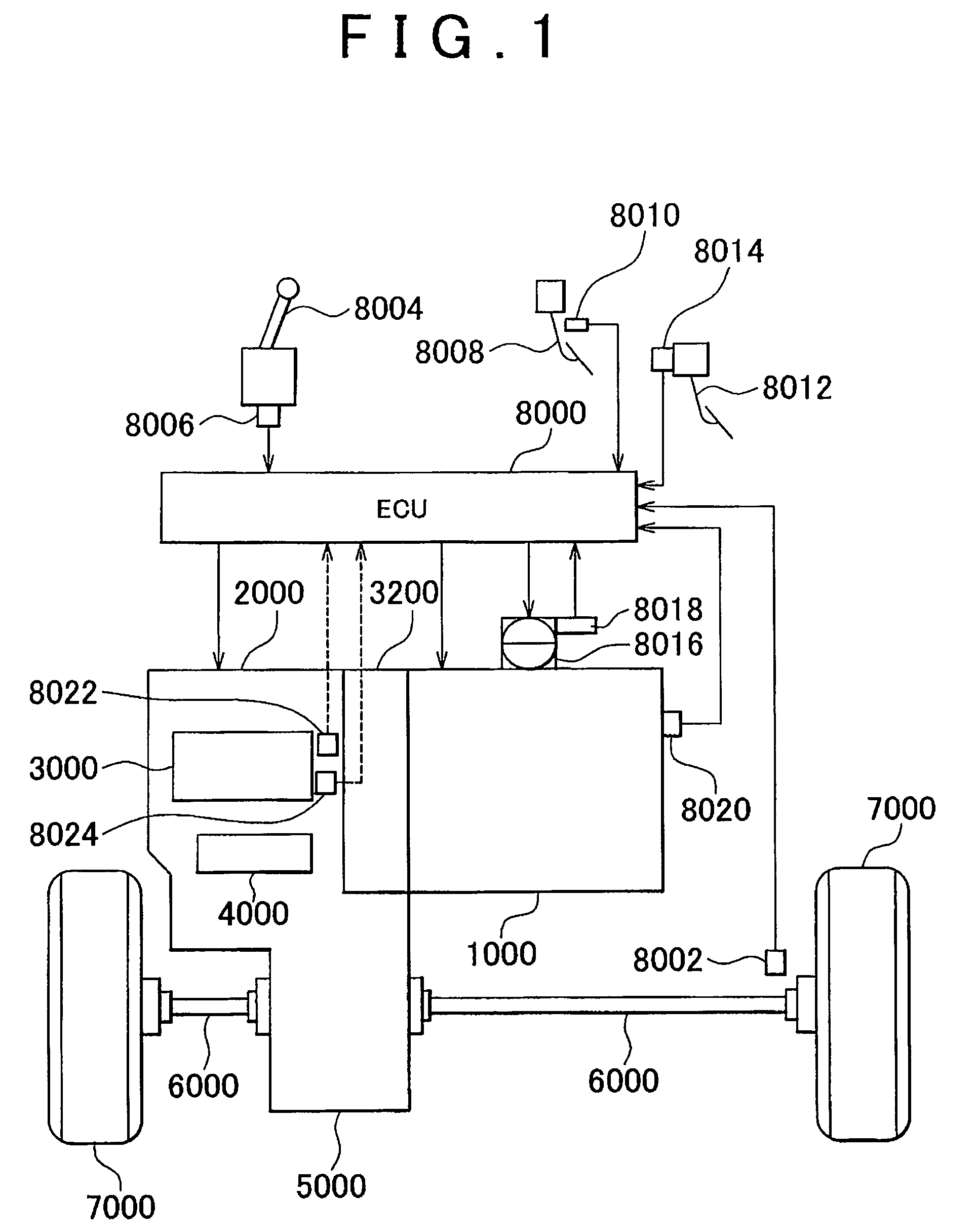
[0029]A vehicle provided with an abnormality determining apparatus according to a first example embodiment of the invention will hereinafter be described with reference to FIG. 1. The vehicle described here is a FF (Front engine Front drive) vehicle, but it may also be a vehicle other than a FF vehicle.

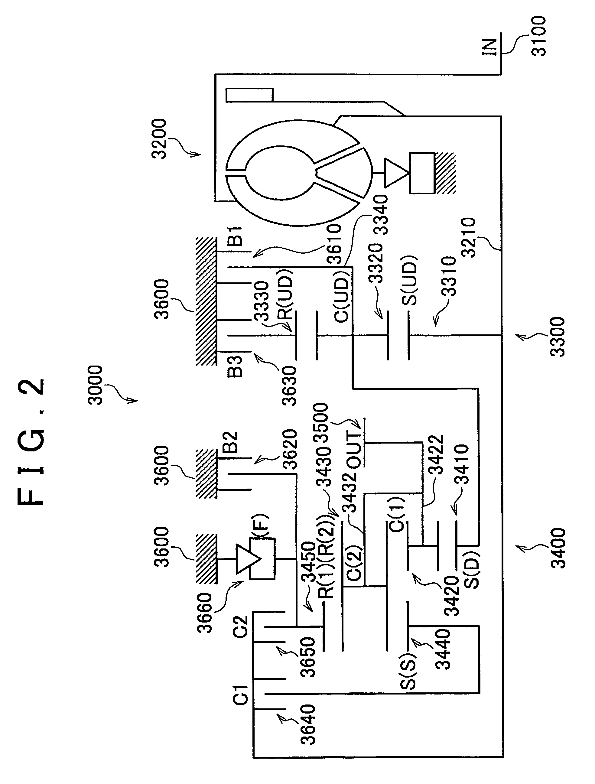
[0030]The vehicle includes an engine 1000, an automatic transmission 2000, a planetary gear unit 3000 that constitutes part of the automatic transmission 2000, a hydraulic pressure circuit 4000 that also constitutes part of the automatic transmission 2000, a differential gear 5000, a drive shaft 6000, front wheels 7000, and an ECU (Electronic Control Unit) 8000.

[0031]The engine 1000 is an internal combustion engine which burns a mixture of air and fuel injected by an injector, not shown, in a combustion chamber of a cylinder. Force generated by the combustion of this air-fuel mixture forces the piston down in the cylinder which in turn rotates a crankshaft.

[0032]The automatic transmis...

second example embodiment

[0069]Hereinafter, a second example embodiment of the invention in which a program that differs from the program executed by the abnormality determining apparatus according to the first example embodiment is executed will be described. The hardware configuration of the vehicle (FIGS. 1, 2, and 3) is the same as it is in the first example embodiment so a detailed description thereof will not be repeated.

[0070]In this second example embodiment, an abnormality of the gear speed of the automatic transmission 2000 is determined by setting the vehicle speed (i.e., output shaft rotation speed NOUT) to the reference rotation speed so that the rotation speed regions using gear ratio determining method (2) whereby the determination is made based on the rotation speed difference do not overlap at all of the gear speeds in the automatic transmission 2000.

[0071]The control structure of the program executed by the ECU 8000 according to this example embodiment will be described with reference to F...

third example embodiment

[0074]Hereinafter, a third example embodiment of the invention in which a program is executed that differs from the program executed by the abnormality determining apparatus according to the first example embodiment will be described. The hardware configuration of the vehicle (FIGS. 1, 2, and 3) is the same as it is in the first example embodiment so a detailed description thereof will not be repeated.

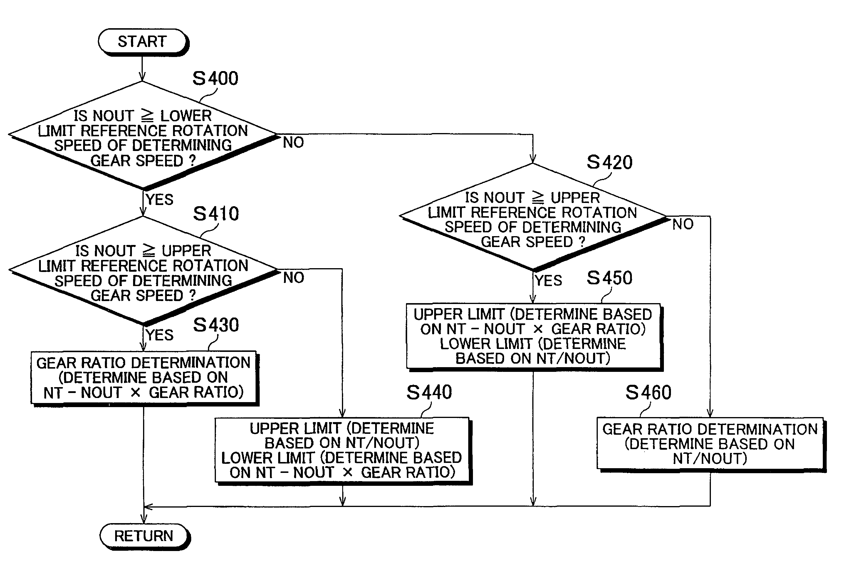
[0075]In this example embodiment, an abnormality of the gear speed of the automatic transmission 2000 is determined by setting a plurality of reference rotation speeds for vehicle speeds (i.e., output shaft rotation speeds NOUT) so that the rotation speed regions using gear ratio determining method (2) whereby the determination is made based on the rotation speed difference do not overlap at adjacent gear speeds in the automatic transmission 2000.

[0076]The control structure of the program executed by the ECU 8000 according to this example embodiment will be described with reference to ...


PUM


Abstract

An ECU executes a program that includes a step of determining whether an output shaft rotation speed NOUT is equal to or greater than a reference rotation speed at which determining regions with all of the gear speeds in a stepped automatic transmission do not overlap, a step of determining that there is an abnormality in the gear speed by dividing the turbine rotation speed NT by the output shaft rotation speed NOUT if the output shaft rotation speed NOUT is not equal to or greater than that reference rotation speed, and a step of determining that there is an abnormality in the gear speed by subtracting a value, which is obtained by multiplying the output shaft rotation speed NOUT by the gear ratio, from the turbine rotation speed NT if the output shaft rotation speed NOUT is equal to or greater than that reference rotation speed.

Description

INCORPORATION BY REFERENCE[0001]The disclosure of Japanese Patent Application No. 2005-360649 filed on Dec. 14, 2005, including the specification, drawings and abstract is incorporated herein by reference in its entirety.BACKGROUND OF THE INVENTION[0002]1. Field of the Invention[0003]The invention relates to an apparatus and method that determines whether an abnormality has occurred in an automatic transmission mounted in a vehicle. More particularly, the invention relates to an apparatus and method that accurately determines whether a gear ratio corresponding to a specified gear speed is not established.[0004]2. Description of the Related Art[0005]An automatic transmission mounted in a vehicle is a combination of a torque converter and a gear type shift mechanism. This automatic transmission is structured so as to automatically establish a gear speed according to an operating state of an engine by selectively switching between applying and releasing a plurality of friction apply el...

Claims


Application Information

Patent Timeline
Patent Type & Authority Patents(United States)
IPC IPC(8): G06F7/00F16H59/40F16H59/42F16H61/12F16H61/68F16H61/684F16H61/686
CPCF16H61/12F16H59/70F16H2061/1208Y10T477/69395Y10T477/693958Y10T477/6243F16H2059/706
Inventor KAWAMURA, TATSUYASUGIMURA, TOSHIOMASAKI, HIDEO
Owner TOYOTA JIDOSHA KK
Why Eureka
Try Eureka