
Powerstroke crossbow

a crossbow and powerstroke technology, applied in the field of crossbows, can solve the problems of sacrificing speed, synchronizing the cam, and reducing the draw length of the crossbow, and achieve the effect of simple manufacturing

Active Publication Date: 2010-11-23
KEMPF JAMES J
View PDF16 Cites 76 Cited by
  • Summary
  • Abstract
  • Description
  • Claims
  • Application Information

AI Technical Summary

Benefits of technology

"This patent describes a low-cost, simple-to-manufacture crossbow with a compact, lightweight construction. It has a reduced ratio of axle-to-axle distance to powerstroke, requires less maintenance, has an increased power stroke, reduces the force required to draw the bowstring, reduces noise associated with launch of a projectile, and provides an increased draw length, allowing the utilization of standard arrows. Additionally, this patent describes a shooting bow with a frame coupled to two limbs extending outwardly away from one another in the direction of shooting, a first string guide member, and a second string guide member. The second string is coupled from a first point on the first string guide, forward of the point where the first string guide is journaled to the first limb, and to a second point on the second string guide, forward of the point where the second string guide is journaled to the second limb. The patent also describes means for retaining the second string in a cocked position and trigger means for causing the retaining means to release the second string."

Problems solved by technology

One drawback associated with such cams is the requirement that the cams be “synchronized” to prevent lateral travel of the rear of the projectile during launch.
This orientation positions the bowstring substantially further back along the rail, drastically decreasing the draw length of the crossbow, simultaneously sacrificing speed, and necessarily increasing the draw weight required to obtain desired performance.
However, although such devices provide for an increased draw length, by drawing the bowstring from the rear of the cams located on the limbs, the draw length is still not effectively maximized.
Additionally, utilizing brackets to locate the cams inward and short of the ends of the limbs, further decreases the potential power of such devices.
Still another drawback with such devices is the inclusion of additional cams located on the frame, which increases cost, weight and maintenance of such devices, as well as adding additional friction to further diminish the potential power of the crossbow.
Such devices also have drawbacks, however, including the pulling of the bowstring from the rear of the cams, which reduces the draw length of the crossbow.
Additionally, Nizov fails to position the bowstring at the end of the rail, thereby sacrificing overall draw length and power.
Such an orientation increases the required length of the rail, while failing to provide any concomitant increase in draw length.
One drawback associated with such devices, however, is the decrease in draw length associated with providing brackets which locate the limb cams rearwardly and inwardly of the limbs.
An additional drawback is that such devices locate the bowstring substantially rearward of the end of the crossbow rail, substantially reducing the draw length and power stroke.
Larger axle-to-axle distances, however, are undesirable, especially in hunting and / or tree stand applications where the increased size and weight associated with the increased axle-to-axle distance would make hunting more difficult.
Still another drawback associated with such devices is the inclusion of pulleys located below the rail of the crossbow.
This additional feature increases the weight, cost and maintenance of such devices, while adding additional friction, further decreasing the potential speed of the crossbow.
As noted above, while there have been several advancements in the field of crossbows, the existing prior art evidences numerous drawbacks, including the failure to utilize the entire potential power stroke of both the forward and rearward ends of the rail, undesirable location of pulleys and cams, and the inclusion of additional frictional parts, further robbing the crossbow projectile of additional speed.

Method used


Image

  • Powerstroke crossbow
  • Powerstroke crossbow
  • Powerstroke crossbow

Examples


Embodiment Construction

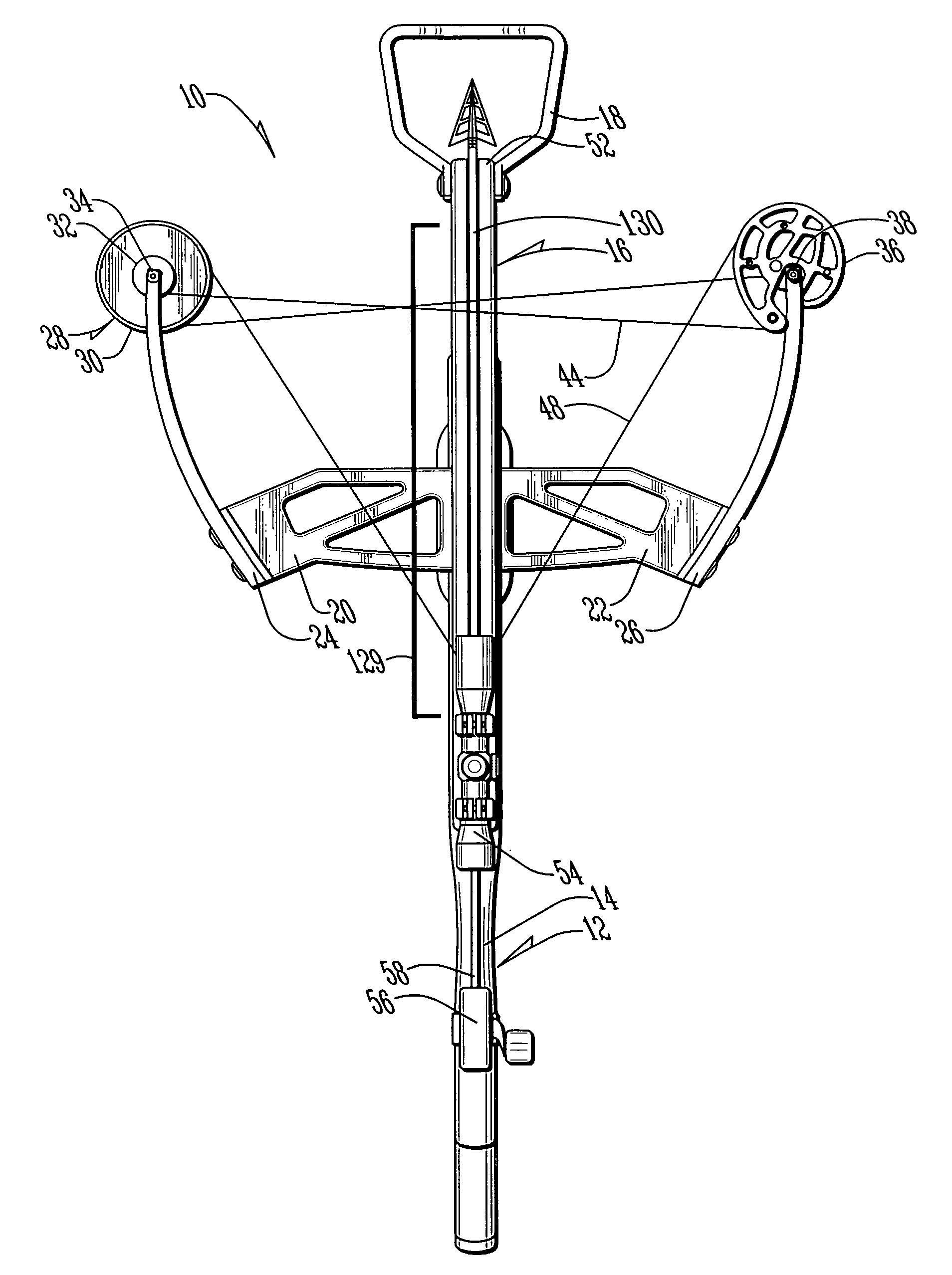
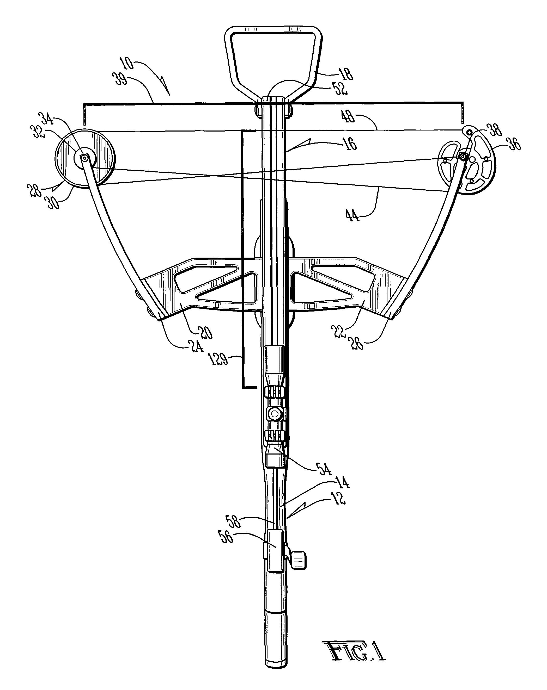
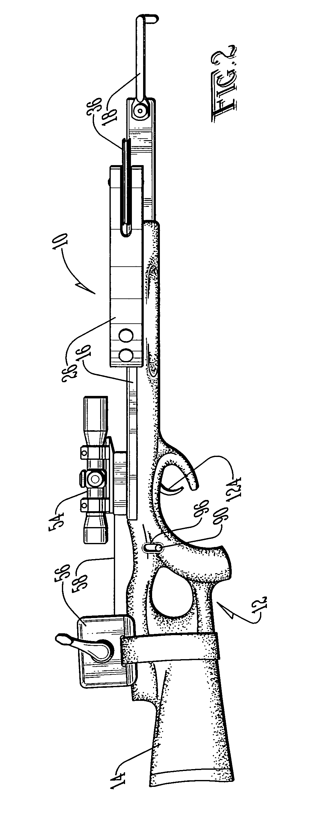
[0032]A crossbow according to the present invention is shown generally as (10) in FIG. 1. As shown in FIGS. 1 and 2, the crossbow (10) is provided with a frame (12) which includes a stock (14) and a rail (16). Although the stock (14) and rail (16) maybe of any type known in the art, in the preferred embodiment the stock (14) is of a composite material construction, and the rail (16) is constructed of aluminum. Alternatively, the crossbow (10) may be of a “railless” design, such as those known in the art.

[0033]The crossbow (10) is provided with a pivotable foot stirrup (18) to facilitate cocking of the crossbow (10). As shown in FIG. 1, the crossbow (10) is also provided with a pair of risers (20) and (22) secured to the rail (16). The risers (20) and (22) are preferably constructed of aluminum to reduce weight. Coupled to the risers (20) and (22) are limbs (24) and (26). The limbs (24) and (26) are constructed and coupled to the risers (20) and (22) in a manner such as that known in...


PUM


Abstract

A crossbow having an increased powerstroke and reduced noise. The powerstroke is increased by inverting the limb orientation from the standard crossbow arrangement and locating string guides at least partially forward and rearward of the ends of the limbs. The bowstring is drawn from the tops of the string guides to maximize the powerstroke, reducing noise and increasing the retained and delivered energy over existing crossbows.

Description

BACKGROUND OF THE INVENTION[0001]1. Field of the Invention[0002]The present invention relates in general to an improved crossbow and, more particularly, to a crossbow having improved speed and reduced noise characteristics.[0003]2. Description of the Prior Art[0004]Crossbows have been known for centuries. By allowing the shooter to mechanically retain the bow in the cocked position, the shooter is provided an advantage over a traditional archer who must utilize muscular force to retain the bow in the cocked position. While crossbow design remained substantially unchanged until the twentieth century, crossbow design has been subject to many recent developments which have dramatically increased performance.[0005]One improvement has been the provision of cams on the crossbow to increase the mechanical advantage associated with the draw of the bowstring. One drawback associated with such cams is the requirement that the cams be “synchronized” to prevent lateral travel of the rear of the...

Claims


Application Information

Patent Timeline
Patent Type & Authority Patents(United States)
IPC IPC(8): F41B5/12
CPCF41B5/123F41B5/1469
Inventor KEMPF, JAMES J.
Owner KEMPF JAMES J
Learn More