Motive power output device, vehicle equipped with the device, and control method for motive power output device

a technology of power output device and motor, which is applied in the direction of electric devices, multi-dynamo-motor starters, engine-driven generators, etc., can solve the problem of difficult to drive the two motors at a proper drive poin

Active Publication Date: 2010-11-23
TOYOTA JIDOSHA KK
View PDF16 Cites 20 Cited by
  • Summary
  • Abstract
  • Description
  • Claims
  • Application Information

AI Technical Summary

Benefits of technology

[0009]The motive power output device in accordance with the first aspect of the invention operates the internal combustion engine based on a predetermined constraint in a range where setting conditions, including the input / output condition that the sum of the electric generator input / output electric power input to or output from the electric generator and the electric motor input / output electric power input to or output from the electric motor be within a range between the input and output restrictions set as a maximum electric power that may be charged into or discharged from the electric storage device, the drive torque condition that the sum of the torque that acts on the driving shaft based on the torque output from the electric generator and the torque that acts on the driving shaft based on the torque output from the electric motor be within a range from the value 0 to the required torque required of the driving shaft, and the electric motor torque alteration condition that the torque output from the electric motor be within a permissible torque range in which alteration from the torque that the electric motor is outputting is permitted, are satisfied. Furthermore, the motive power output device controls the internal combustion engine, the electric generator, and the electric motor so that the required torque is output to the driving shaft. Therefore, the internal combustion engine, the electric generator, and the electric motor can be driven by taking into account not only the input and output restrictions of the electric storage device but also the permissible torque range that is permitted when the torque of the electric motor is altered. As a result, the electric generator and the electric motor can be more properly driven.
[0011]Besides, in the motive power output device in accordance with the first aspect of the invention, the electric motor torque alteration condition may be a condition in which the permissible torque range is a range defined by a torque that is larger by an alteration torque than the torque that the electric motor is outputting and a torque that is smaller than the value 0 by the alteration torque. In this case, the motive power output device may further include a voltage adjustment device that allows electric power to be sent and received between the electric storage device, the electric generator and the electric motor by adjusting the voltage of a side of the electric generator and the electric motor relative to the voltage of a side of the electric storage device, and the electric motor torque alteration condition may be a condition in which the permissible torque range is a range obtained by using a first toque as the alteration torque when the voltage of the side of the electric generator and the electric motor is made equal to the voltage of the side of the electric storage device by the voltage adjustment device, and may be a condition in which the permissible torque range is a range obtained by using a second torque that is larger than the first torque as the alteration torque when the voltage of the side of the electric generator and the electric motor is made higher than the voltage of the side of the electric storage device by the voltage adjustment device. This construction makes it possible to more properly drive the electric generator and the electric motor according to the operating state of the voltage adjustment device.
[0014]Since the vehicle in accordance with the second aspect of the invention is equipped with any one of the foregoing motive power output devices in accordance with the first aspect of the invention, the vehicle achieves substantially the same effects as the those achieved by the motive power output device in accordance with the first aspect of the invention, for example, the effect of being able to drive the internal combustion engine, the electric generator, and the electric motor by taking into account not only the input and output restrictions of the electric storage device but also the permissible torque range that is permitted at the time of alteration of the torque of the electric motor, and, as a result of this effect, the effect of being able to more properly drive the electric generator and the electric motor, and the like.
[0016]The motive power output device control method in accordance with the third aspect of the invention operates the internal combustion engine based on a predetermined constraint in a range where setting conditions, including the input / output condition that the sum of the electric generator input / output electric power input to or output from the electric generator and the electric motor input / output electric power input to or output from the electric motor be within a range between the input and output restrictions set as a maximum electric power that may be charged into or discharged from the electric storage device, the drive torque condition that the sum of the torque that acts on the driving shaft based on the torque output from the electric generator and the torque that acts on the driving shaft based on the torque output from the electric motor be within a range from the value 0 to the required torque required of the driving shaft, and the electric motor torque alteration condition that the torque output from the electric motor be within a permissible torque range in which alteration from the torque that the electric motor is outputting is permitted, are satisfied. Furthermore, the control method controls the internal combustion engine, the electric generator, and the electric motor so that the required torque is output to the driving shaft. Therefore, the internal combustion engine, the electric generator, and the electric motor can be driven by taking into account not only the input and output restrictions of the electric storage device but also the permissible torque range that is permitted when the torque of the electric motor is altered. As a result, the electric generator and the electric motor can be more properly driven.

Problems solved by technology

However, in the foregoing motive power output device, when the required torque sharply changes, it sometimes becomes difficult to drive the two motors at a proper drive point.

Method used


Image

  • Motive power output device, vehicle equipped with the device, and control method for motive power output device
  • Motive power output device, vehicle equipped with the device, and control method for motive power output device
  • Motive power output device, vehicle equipped with the device, and control method for motive power output device

Examples


Embodiment Construction

[0028]Next, best modes for carrying out the invention will be described with reference to embodiments.

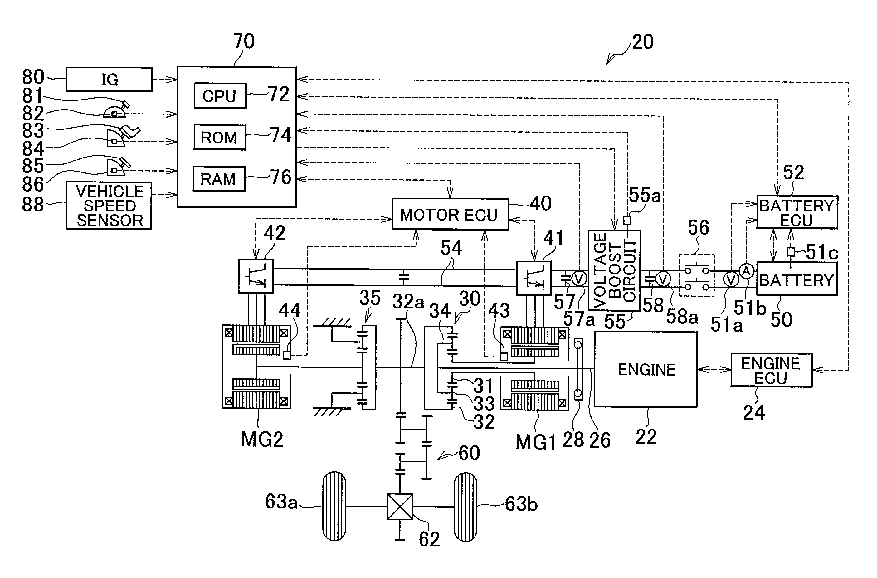
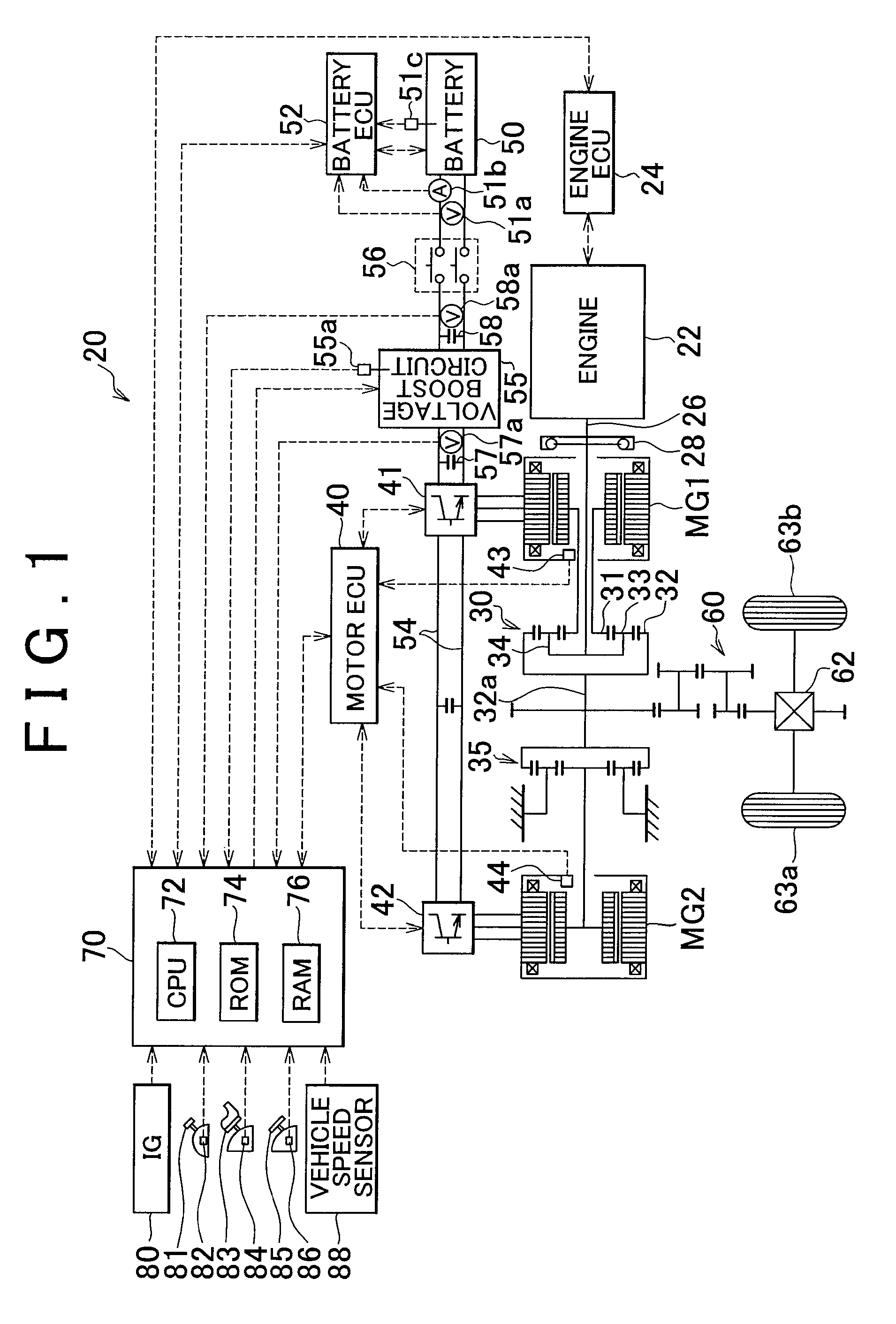
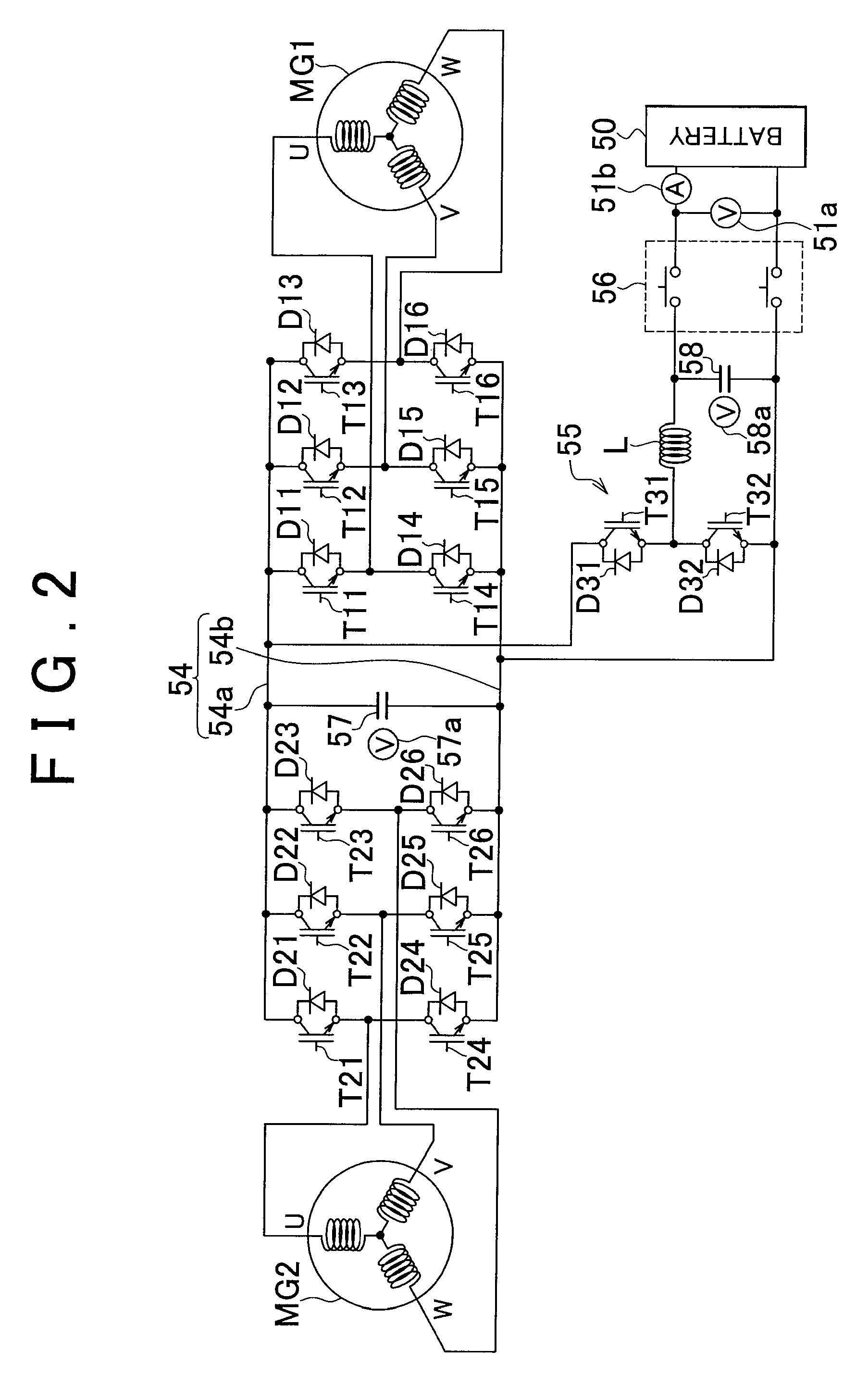
[0029]FIG. 1 is a construction diagram showing a general construction of a hybrid motor vehicle 20 that is an embodiment of the invention. FIG. 2 is a construction diagram showing a general construction of an electric appliance drive system that includes electric motors MG1, MG2. The hybrid motor vehicle 20 of the embodiment, as shown in FIG. 1, includes: an engine 22; a three-shaft type motive power distribution / integration mechanism 30 connected to a crankshaft 26 as an output shaft of the engine 22 via a damper 28; an electric motor MG1 capable of generating electric power which is connected to the motive power distribution / integration mechanism 30; an electric motor MG2 connected via a speed reduction gear 35 to a ring gear shaft 32a as a driving shaft connected to the motive power distribution / integration mechanism 30; inverters 41, 42 capable of converting direct current into ...


PUM


Abstract

A torque command for a first motor is set by setting a maximum torque restriction and a minimum torque restriction in a range, where the sum of the torques output from the first and second motors to a driving shaft be within a range from 0 to a required torque, the sum of the electric powers input from or output to the first and second motors be within a range of input and output restrictions of a battery, and the torque of the second motor be within a range from a value smaller than 0 by the permissible maximum amount of change to the sum of the permissible maximum amount of change and the previous torque command. A torque command for the second motor is set so that the required torque is output to the driving shaft within a range of the input and output restrictions of the battery.

Description

INCORPORATION BY REFERENCE[0001]The disclosure of Japanese Patent Application No. 2008-095351 filed on Apr. 1, 2008 including the specification, drawings and abstract is incorporated herein by reference in its entirety.BACKGROUND OF THE INVENTION[0002]1. Field of the Invention[0003]The invention relates to a motive power output device, and a vehicle equipped with the device as well as a control method for the motive power output device.[0004]2. Description of the Related Art[0005]There has been proposed a motive power output device which includes an engine, a planetary gear whose carrier is connected to a crankshaft of the engine, and whose ring gear is connected to a driving shaft linked to an axle shaft, a motor MG1 connected to a sun gear of the planetary gear, and a motor MG2 connected to the driving shaft, and which controls the engine and two electric motors MG1, MG2 so as to output a required torque that is required for the traveling of the vehicle while operating the engine ...

Claims


Application Information

Patent Timeline
Patent Type & Authority Patents(United States)
IPC IPC(8): B60K6/20B60L50/16
CPCB60K6/365B60K6/52B60L15/20B60K6/445Y02T10/7275B60L2240/423B60L2240/486B60W10/08B60W10/26B60W20/00B60W2710/083B60W2710/105F16H3/727F16H2037/0866Y02T10/6265Y02T10/646Y02T10/648Y02T10/6239B60L3/04B60L3/06B60L15/007B60L15/2054B60L2210/40B60L2240/12B60L2240/421B60L2240/441B60L2240/443B60L2250/24B60L2250/26B60L50/16B60L50/61B60L58/12B60L58/15Y02T10/62Y02T10/64Y02T10/70Y02T10/7072Y02T10/72B60L3/0046B60W20/13
Inventor ITOH, TAKAO
Owner TOYOTA JIDOSHA KK
Why Eureka
Try Eureka