Device for selecting a hydraulic circuit overall capacity
- Summary
- Abstract
- Description
- Claims
- Application Information
AI Technical Summary
Benefits of technology
Problems solved by technology
Method used
Image

Examples
first embodiment
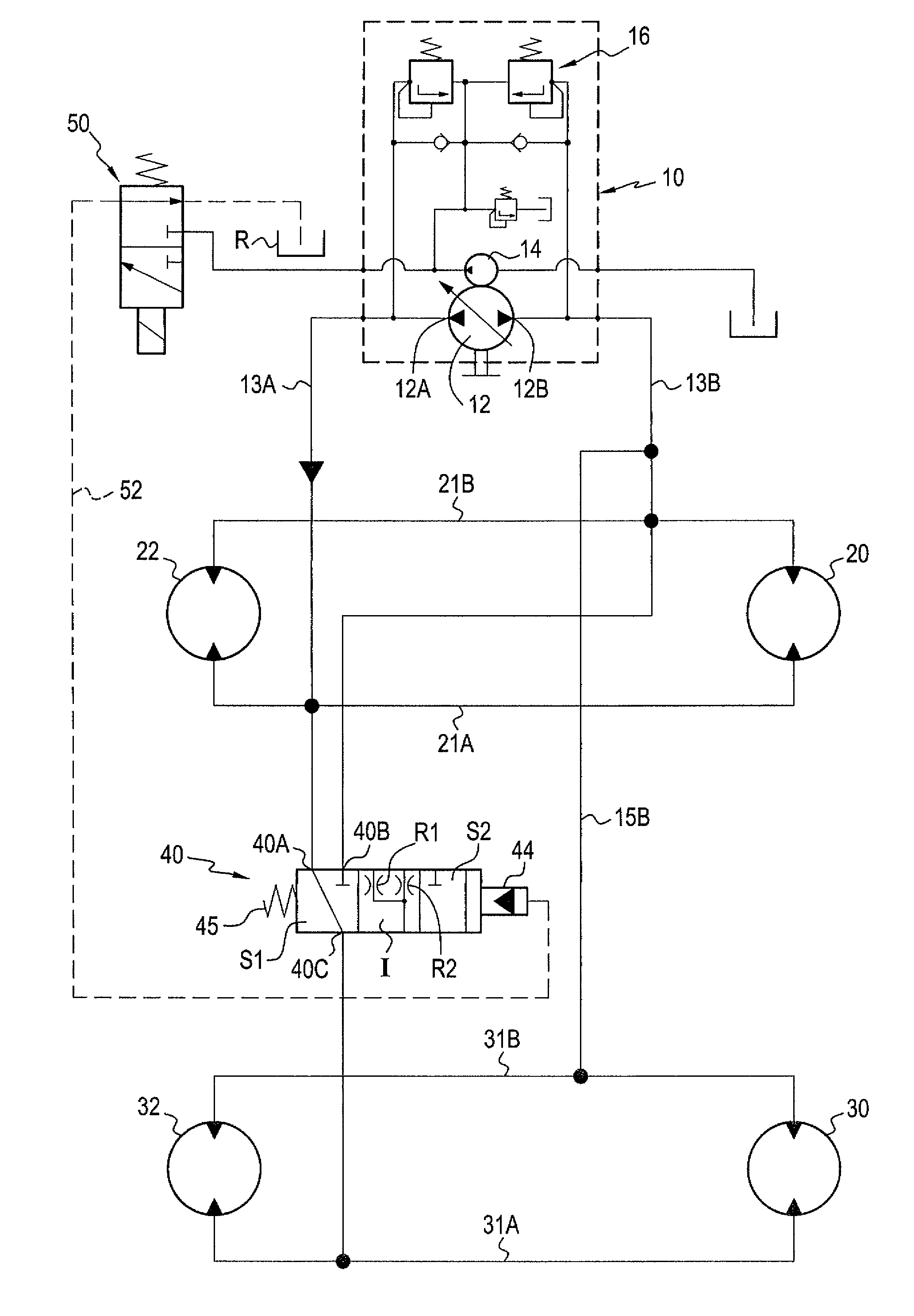
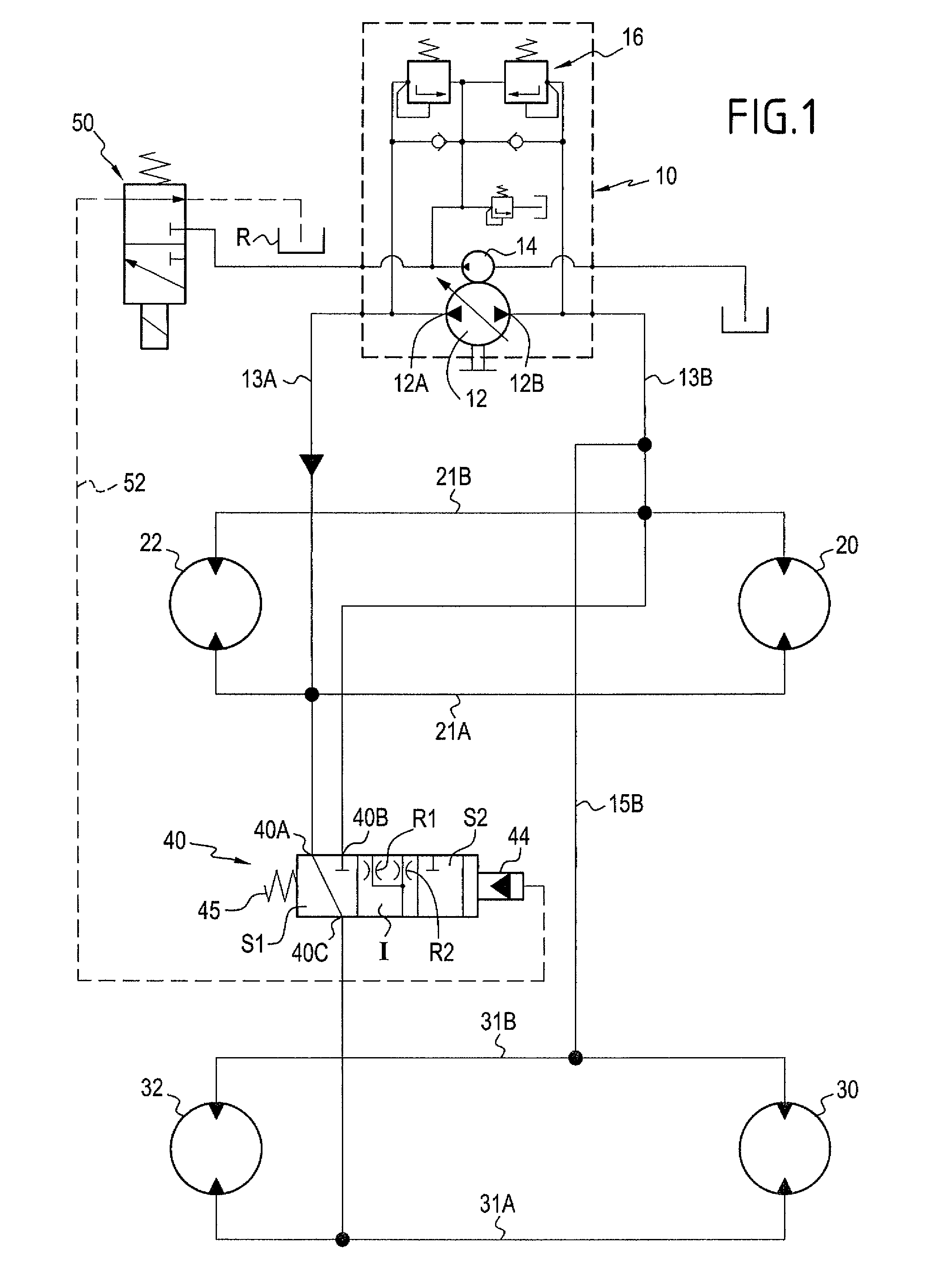
[0053]Similarly, the circuit includes a third main duct 31A and a fourth main duct 31B to which the motors 30 and 32 of the second set are connected in parallel. In the first embodiment shown in FIG. 1, the fourth main duct 31B is connected continuously to the second main duct 21B, via an interconnection duct 15B external to the selector 40.
[0054]The circuit includes a selector device for selecting its overall cubic capacity, which device, depending on its configuration, can make the motors of the second set active or inactive.
[0055]This device comprises a selector 40 which, in the first embodiment shown in FIG. 1 is a three-port valve, having its first port 40A connected to the first main duct 21A, its second port 40B connected to the second main duct 21B, and its third port 40C connected to the third main duct 31A. FIG. 1 shows the valve 40 in its first stable position S1, in which the first and second ports 40A and 40C are interconnected while being isolated from the second port ...
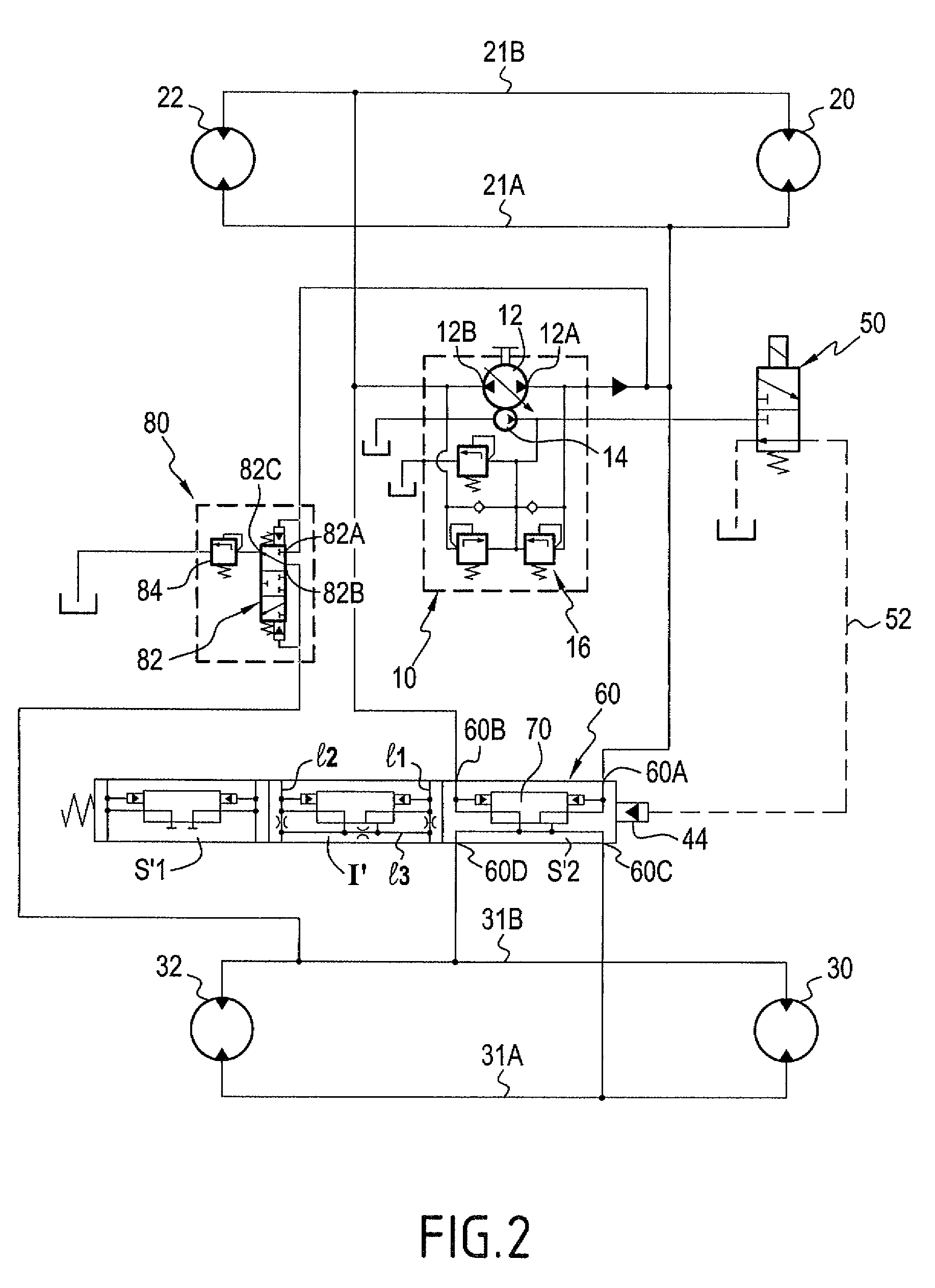
second embodiment
[0063]the invention is described below, with reference to FIG. 2. The circuit shown in FIG. 2 also serves to drive in translation a vehicle that has two axles, each of which has two driven wheels. There can also be seen the pump unit 10, with the main pump 12 and its two orifices 12A, 12B, as well as the booster pump 14 and the pressure limiters 16. There can also be seen the two motors of the first set 20 and 22, and the first main duct 21A that is connected to the orifice 12A and that feeds the motors 20 and 22 in parallel, as well as the second main duct 21B that is connected to the second orifice 12B of the pump and that makes it possible for the motors 20 and 22 to be discharged in parallel.
[0064]There can also be seen the motors 30 and 32 of the second set, as well as the third main duct 31A and the fourth main duct 31B that serve to discharge and to feed in parallel the motors 30 and 32.
[0065]For selecting the overall cubic capacity of the circuit, said circuit further includ...
PUM
 Abstract
Description
Claims
Application Information
 - Generate Ideas
- Intellectual Property
- Life Sciences
- Materials
- Tech Scout
- Unparalleled Data Quality
- Higher Quality Content
- 60% Fewer Hallucinations
Browse by: Latest US Patents, China's latest patents, Technical Efficacy Thesaurus, Application Domain, Technology Topic, Popular Technical Reports.
© 2025 PatSnap. All rights reserved.Legal|Privacy policy|Modern Slavery Act Transparency Statement|Sitemap|About US| Contact US: help@patsnap.com