Exhaust system slip joint

a technology of exhaust system and slip joint, which is applied in the direction of screw threaded joints, machines/engines, mechanical equipment, etc., can solve problems such as unfulfilled needs, and achieve the effect of reliable and durable sealing of exhaust systems and improved durability

Active Publication Date: 2010-11-23
CUMMINS INTPROP INC
View PDF17 Cites 24 Cited by
  • Summary
  • Abstract
  • Description
  • Claims
  • Application Information

AI Technical Summary

Benefits of technology

[0009]In view of the foregoing, an advantage of the present invention is in providing an exhaust system with an improved slip joint.
[0010]Another advantage of the present invention is in providing such an exhaust system with a slip joint that provides a more reliable and durable sealing of exhaust systems.
[0011]In accordance with one embodiment of the present invention, an exhaust system of an internal combustion engine includes a slip joint with a female section having an opening with an inner diameter, a male section having an outer diameter smaller than the inner diameter of the opening of the female section, the male section being at least partially received in the female section, a wear sleeve disposed between the female section and the male section, and at least one seal contacting the wear sleeve and at least one of the female section and the male section, to seal the slip joint. In one implementation of the exhaust system, a diametric clearance between the inner diameter of the female section and the outer diameter of the male section is less than approximately 0.2 mm, and is preferably approximately 0.062 mm.
[0012]In another embodiment, the wear sleeve includes a slit extending along an axial length of the wear sleeve, the slit extending at an angle relative to the axial length of the wear sleeve. In another embodiment, the wear sleeve includes a bent flange that abuts against an end of the male section. In accordance with still another embodiment, the wear sleeve is made of a stainless steel or a nickel alloy, and has a cross sectional thickness of approximately 0.005 to 0.05 inch, preferably approximately 0.01 inch.
[0013]In accordance with one embodiment of the present invention, the seal has a U-shaped cross section, and the male section includes a groove in which the seal is received. In another embodiment, the male section may include a plurality of grooves, and a plurality of seals are received therein, each seal contacting the wear sleeve to seal the slip joint. In another embodiment, the seal has a substantially J-shaped cross section with a C-shaped portion and a resilient leg portion, the resilient leg portion including a curved portion that abuts against the female section. In such an embodiment, the C-shaped portion may be implemented to be fluidically open to the opening of the female section so that gas pressure in the female section expands the C-shaped portion outwardly. In yet another embodiment, the seal has a substantially truncated S-shape.
[0014]The seal of the exhaust system of the present invention may be implemented to include a slit. The seal may be made of a nickel alloy having a material thickness of approximately 0.005 to 0.05 inch, and preferably of approximately 0.01 inch. The male section has a reduced diameter protrusion at least partially defined by a vertical lip, the protrusion and the vertical lip at least partially defining a seal chamber between the male section and the female section, the seal being positioned in the seal chamber. To improve durability, the female section, the male section, the seal and / or the wear sleeve is coated with TiAlN or Fe3O4 in accordance with another embodiment of the present invention.

Problems solved by technology

However, there still exists an unfulfilled need for an improved exhaust system slip joint that provides a more reliable and durable sealing of exhaust systems.

Method used


Image

  • Exhaust system slip joint
  • Exhaust system slip joint
  • Exhaust system slip joint

Examples


Embodiment Construction

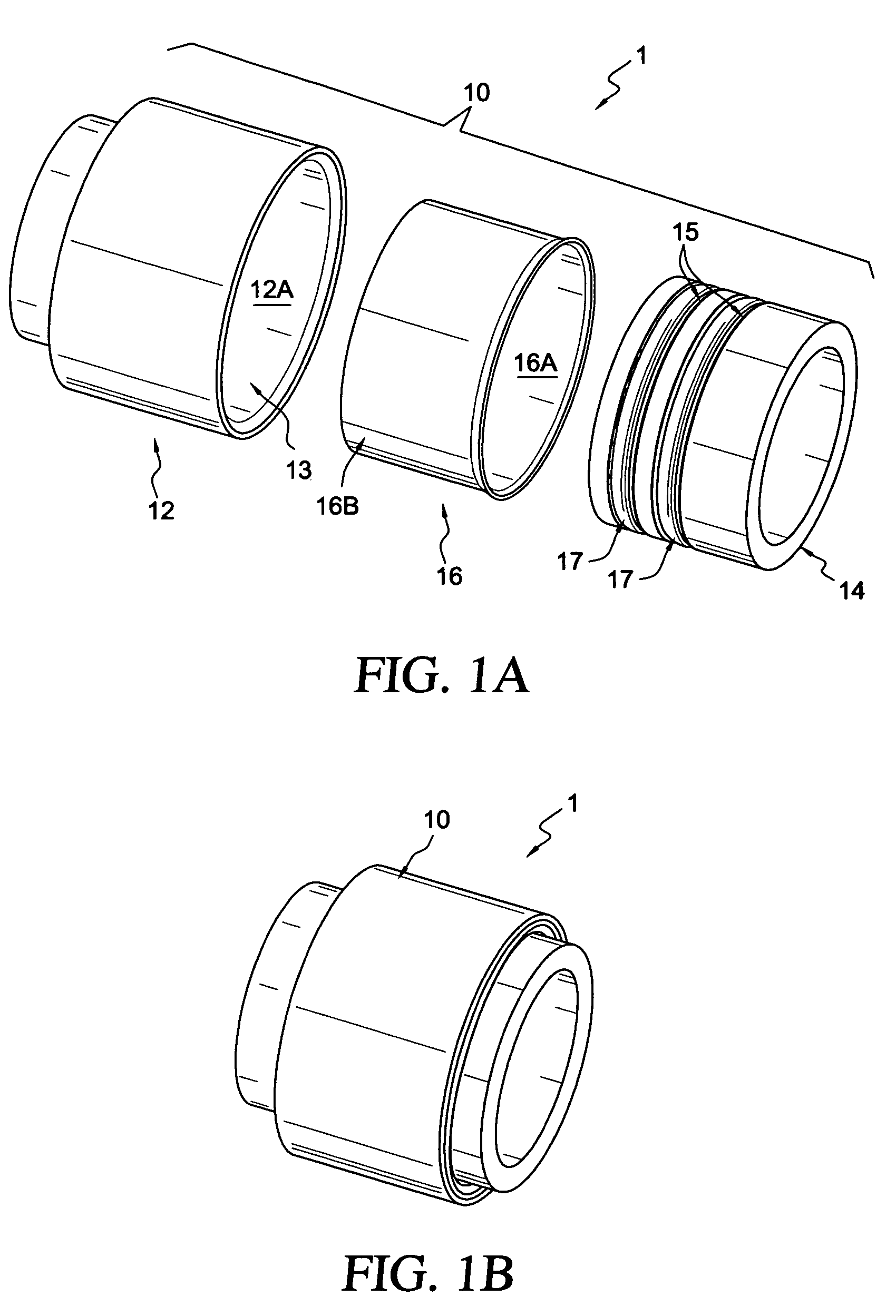
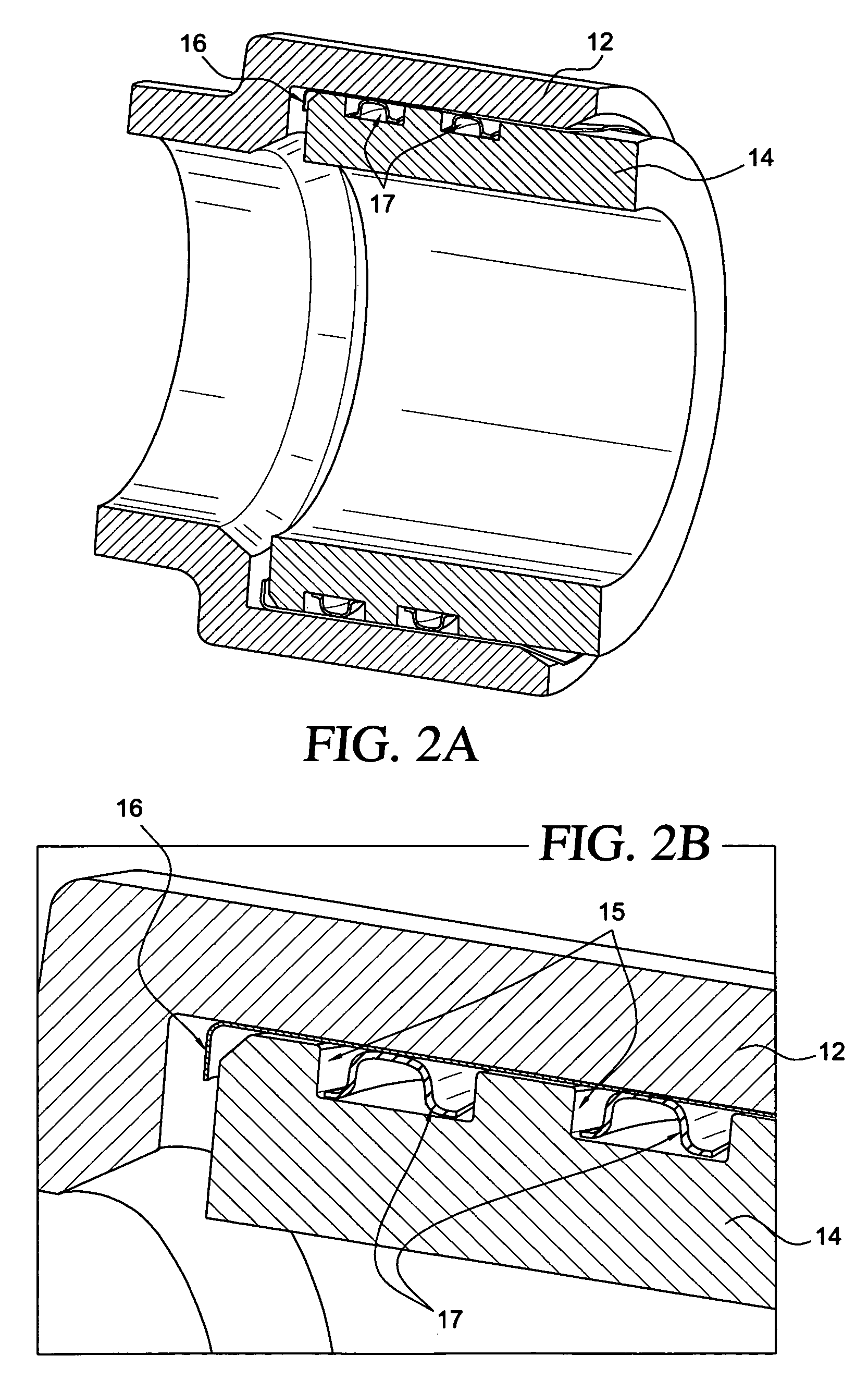
[0049]FIG. 1A shows an exploded assembly view of an exhaust system 1 of an internal combustion engine that incorporates a slip joint 10 in accordance with one embodiment of the present invention, such as an exhaust manifold. The illustrated slip joint 10 includes a female section 12 that is substantially tubular in shape with an inner surface 12A that defines an opening 13 which extends therethrough. The inner diameter of the opening 13 of the female section 12 is sized to movably receive the male section 14 therein. Correspondingly, the opening 13 of the female section 12 is sized slightly larger than the outer diameter of the male section 14. Disposed between the female section 12 and the male section 14 is a wear sleeve 16 which is also size to be received within the female section 12, and sized to receive the male section 14 therein. The male section 14 includes annular grooves 15 in the outer surface thereof in which seal rings 17 are received. The male section 14, together wit...


PUM


Abstract

An exhaust system of an internal combustion engine includes a slip joint with a female section having an opening with an inner diameter, a male section having an outer diameter smaller than the inner diameter of the opening of the female section, the male section being at least partially received in the female section, a wear sleeve disposed between the female section and the male section, and at least one seal contacting the wear sleeve and at least one of the female section and the male section, to seal the slip joint.

Description

[0001]This application claims priority to U.S. Provisional Application No. 60 / 711,411, filed Aug. 26, 2005, the contents of which are incorporated herein by reference.BACKGROUND OF THE INVENTION[0002]1. Field of the Invention[0003]The present invention relates to slip joints of an exhaust system and seals used therein.[0004]2. Description of Related Art[0005]U.S. Pat. No. 6,220,605 issued to Becker, Jr. discloses a slip joint for an engine exhaust system having a male and female manifold section which utilizes a sleeve assembly that is disposed about one of the manifold sections. The sleeve assembly has a positioning portion and locating portion. The positioning portion is in sealing engagement with one of the manifold sections and the locating portion is in resiliently sealing engagement with the other manifold section.[0006]U.S. Pat. No. 6,446,978 discloses a resilient seal having an annular curved region with a generally C-shaped cross section, and a pair of annular leg regions. ...

Claims


Application Information

Patent Timeline
Patent Type & Authority Patents(United States)
IPC IPC(8): F16L15/02
CPCF01N13/1811F01N13/1827F16L21/035F16L27/12F16L57/005F16L57/06F01N2260/10F01N2510/00F16L27/1275
Inventor JOHNSTON, SPENCER C.ALDEN, GLEN R.STORKMAN, WILLIAM R.DUKE, JAMES R.MOSHIER, BENJAMIN J.IRISH, REID M.DORAISWAMY, DEVARAJKOSINSKI, MICHAEL T.
Owner CUMMINS INTPROP INC
Why Eureka
Try Eureka