Optical system for optical disc

a technology of optical discs and optical systems, applied in the field of optical systems, can solve the problems of deteriorating the quality of the recording (optical) signal and the reproducing, difficult to achieve the correction of astigmatism, and difficulty in using optical systems for optical discs such as dvds, etc., to achieve the effect of sufficient suppression of aberrations

Inactive Publication Date: 2010-11-23
HOYA CORP
View PDF22 Cites 0 Cited by
  • Summary
  • Abstract
  • Description
  • Claims
  • Application Information

AI Technical Summary

Benefits of technology

[0014]The present invention is advantageous in that it provides an optical system for optical discs configured to sufficiently suppress aberrations without using a coupling lens.
[0017]Since the attitude of the objective lens can be changed concurrently with tracking shift movement of the objective lens by the tracking operation, astigmatism caused by the tracking shift movement of the objective lens can be suppressed. Consequently, recording / reproducing operation for an optical disc (which requires a relatively high numerical aperture) can be performed with high accuracy.
[0018]It is noted that the correction of the astigmatism can be attained by only changing the attitude of the objective lens in the optical system, and it is not required to change the configuration of the objective lens for the correction of the astigmatism.
[0028]Since the attitude of the objective lens can be changed concurrently with tracking shift movement of the objective lens by the tracking operation, astigmatism caused by the tracking shift movement of the objective lens can be suppressed. Consequently, recording / reproducing operation for an optical disc (which requires a relatively high numerical aperture) can be performed with high accuracy.
[0049]Since the attitude of the objective lens can be changed concurrently with tracking shift movement of the objective lens by the tracking operation, astigmatism caused by the tracking shift movement of the objective lens can be suppressed. Consequently, recording / reproducing operation for an optical disc (which requires a relatively high numerical aperture) can be performed with high accuracy.

Problems solved by technology

In particular, aberrations having an asymmetric property such as a coma and astigmatism are main factors that deteriorate quality of a recording (optical) signal and a reproducing (optical) signal.
By contrast, sufficient correction of another aberration having an asymmetric property, i.e. astigmatism, is very difficult even if the objective lens of which both surfaces are asymmetrical surfaces is employed in the optical system.
In other words, the optical system can not be used for an optical disc (such as a DVD) which has a relatively large recording density and requires a relatively small beam spot diameter.
However, such a conventional CD / DVD-compatible optical system can not correct a coma which changes depending on the thickness of the cover layer of the optical disc.
Further, astigmatism is not corrected in the CD / DVD compatible optical system as in the case of the optical system of each of the publications.

Method used


Image

  • Optical system for optical disc
  • Optical system for optical disc
  • Optical system for optical disc

Examples


first embodiment

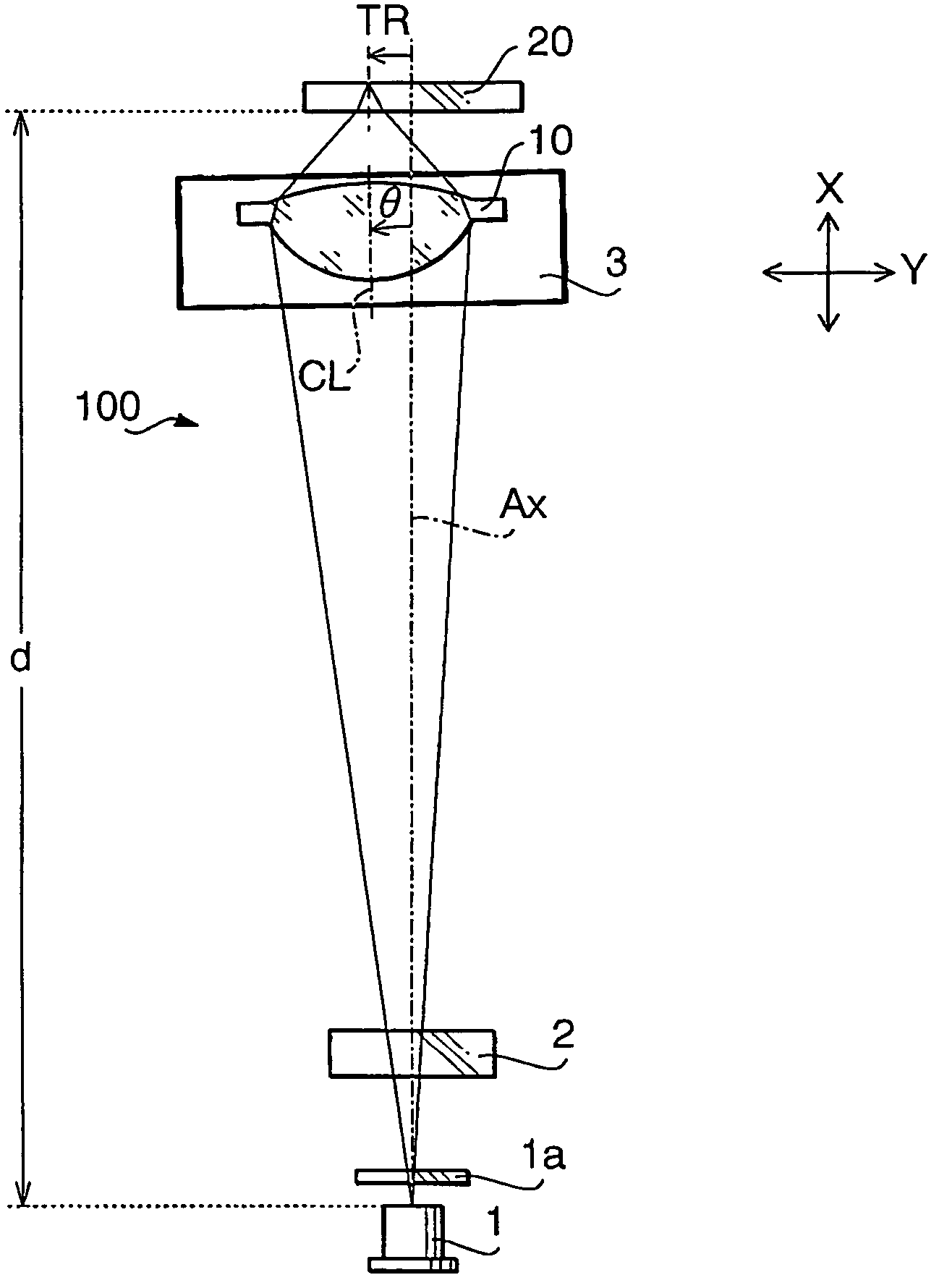
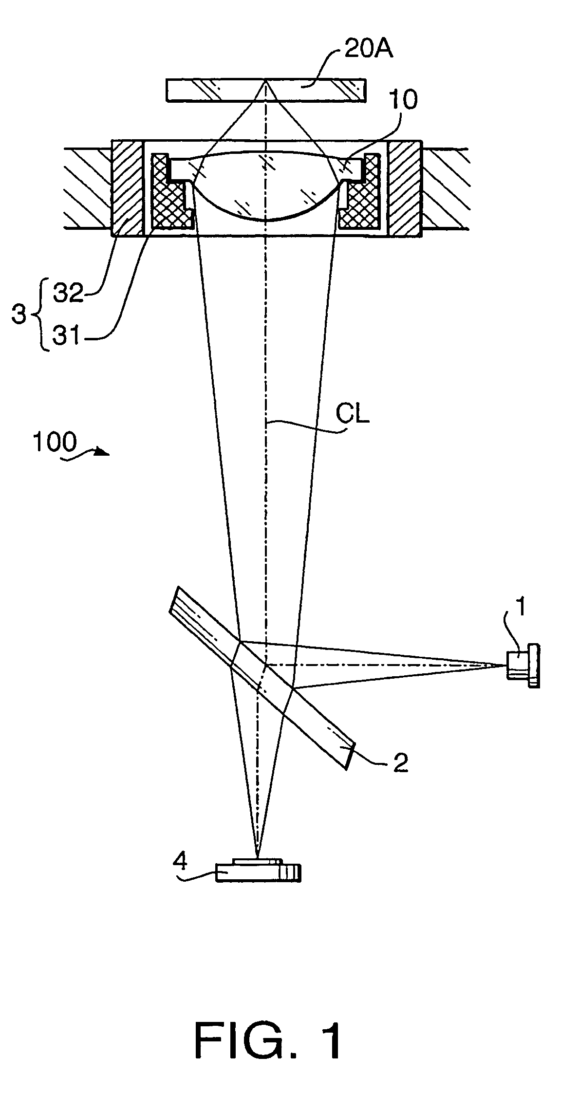
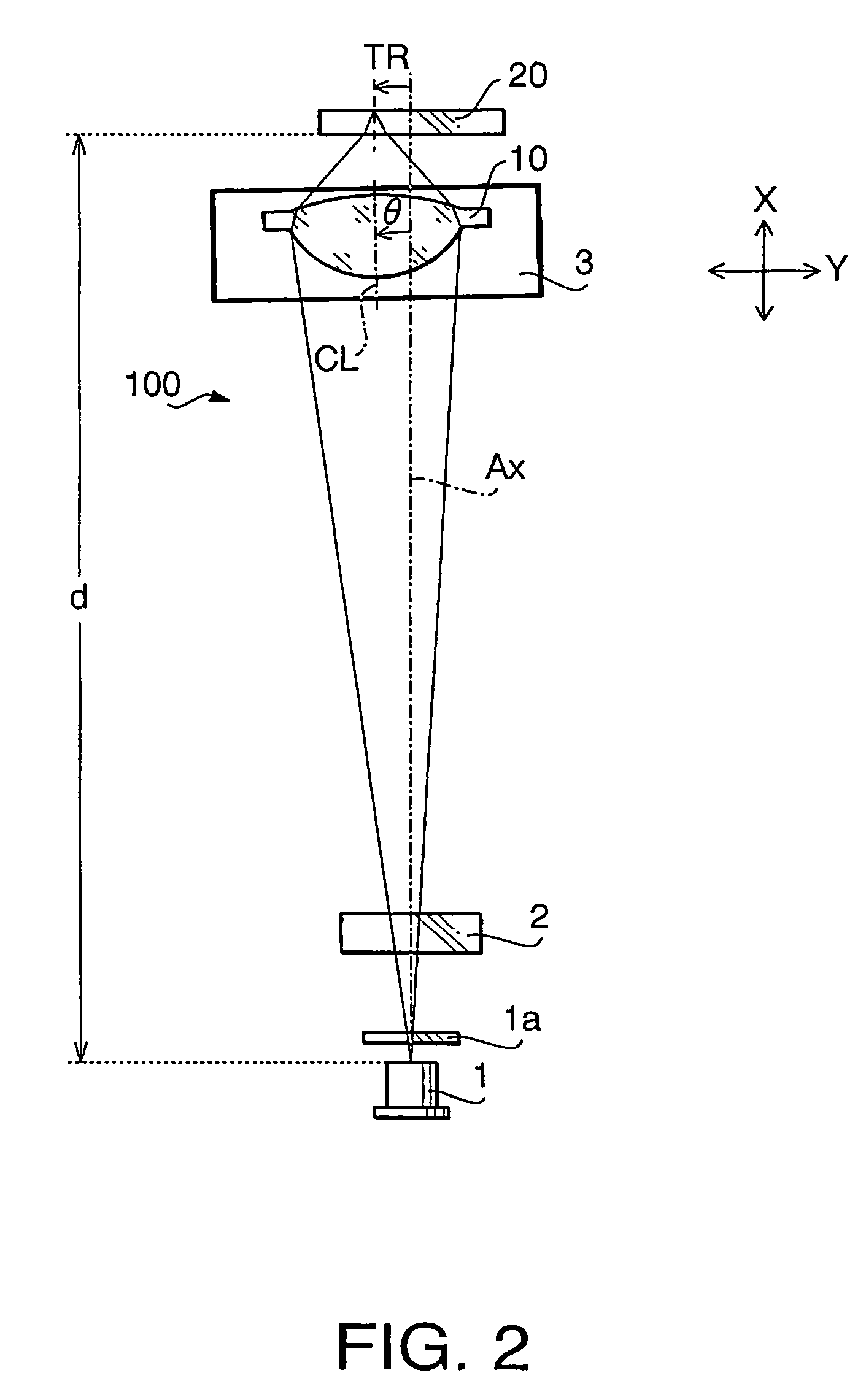
[0064]FIG. 1 schematically shows an optical system 100 according to a first embodiment of the invention. The optical system 100 is used for recording data to and / or reproducing data from an optical disc 20A (e.g. DVD) having a relatively high recording density and a relatively thin cover layer. The optical system 100 is employed in an optical disc drive which records data to and / or reproduces data from the optical disc 20A.

[0065]As shown in FIG. 1, the optical system 100 is provided with a light source 1, a beam splitter 2, a lens actuating mechanism 3, a sensor 4 and an objective lens 10. The optical system 100 is configured as a finite optical system which does not use a coupling lens. That is, a laser beam emitted by the light source 1 is converged only by the objective lens 10.

[0066]The light source 1 emits the laser beam having a relatively short wavelength suitable for the optical disc 20A so that the laser beam passed through the beam splitter 2 and the objective lens 10 form...

second embodiment

[0093]FIG. 3 schematically shows an optical system 200 according to a second embodiment of the invention. The optical system 200 is used for recording data to and / or reproducing data from a plurality of types of optical discs having different thicknesses of cover layers. In FIG. 3, to elements which are similar to those shown in FIG. 1, the same reference numbers are assigned, and the detailed description thereof will not be repeated.

[0094]As examples of the plurality of types of optical discs, the optical disc 20A (e.g. DVD) and an optical disc 20B (e.g. CD or CD-R) which has a lower recording density than that of the optical disc 20A and has a cover layer thicker than that of the optical disc 20A are illustrated. The optical system 200 is employed in an optical disc drive which records data to and / reproduces data from the plurality of types of optical discs.

[0095]As shown in FIG. 3, the optical system 200 includes a light source 1D, a diffraction grating 5, the beam splitter 2, th...

first example

[0132]An optical system according to a first example has a configuration described in the first embodiment with reference to FIG. 1. Therefore, the first example will be explained with reference to FIG. 1. Table 1 shows performance specifications of the optical system 100 according to the first example, and Table 2 shows a numerical configuration of the optical system 100 according to the first example.

[0133]

TABLE 1Optical Disc 20ADESIGN655WAVELENGTH λ (nm)NA0.620M−0.143THICKNESS OF COVER0.60LAYER (mm)

[0134]In Table 1, M represents the magnification, the design wavelength is a wavelength suitable for the recordation / reproduction of the optical disc being used, NA is a numerical aperture on the optical disc side. These symbols are also applied to similar tables in concrete examples indicated below.

[0135]

TABLE 2SurfaceNumberrdnν#00.50#10.251.51664.2#211.32#31.1291.201.54455.7#4−1.9750.80#50.601.58529.9#6—

[0136]In Table 2, “surface number” represents a surface number of each surface of...


PUM

PropertyMeasurementUnit
distanceaaaaaaaaaa
thickaaaaaaaaaa
thicknessesaaaaaaaaaa

Abstract

There is provided an optical system for an optical disc which requires a numerical aperture larger than or equal to 0.60. The optical system is provided with a light source, an objective lens, and a driving system that controls a position and an attitude of the objective lens. The driving system operates to move the objective lens in a direction perpendicular to a central axis of the objective lens for a tracking operation, and to change the attitude of the objective lens during the tracking operation so that the central axis on a light source side tilts toward the light source.

Description

BACKGROUND OF THE INVENTION[0001]The present invention relates to an optical system used to record data to and / or reproduce data from one or more types of optical discs having different thicknesses of cover layers and / or different data recording densities.[0002]There are various types of optical discs such as a CD (compact disc) and a DVD (digital versatile disc). The DVD has the cover layer thinner than that of the CD, and has a data recording density higher than that of the CD. For supporting both of the CD and DVD, the optical system for optical discs (i.e. an optical pick-up) is required to correct a spherical aberration which changes depending on the thickness of the cover layer of an optical disc being used and to change NA (numerical aperture) of a light beam so as to attain an effective beam diameter suitable for recording / reproducing operation of the optical disc being used.[0003]In general, the optical system for optical discs has a light source for emitting the light beam...

Claims


Application Information

Patent Timeline
Patent Type & Authority Patents(United States)
IPC IPC(8): G11B7/00G11B7/135G02B13/18G11B7/09G11B7/095
CPCG11B7/0956G11B2007/0006G11B7/09
Inventor TAKEUCHI, SHUICHI
Owner HOYA CORP
Why Eureka
Try Eureka