
Method and device for automatically triggering a vehicle deceleration

a technology of automatic braking and vehicle deceleration, which is applied in the direction of pedestrian/occupant safety arrangement, anti-collision system, special data processing application, etc., can solve the problem that full braking is especially risky for the passengers of the vehicle, and achieve the effect of reducing the consequences of an imminent collision

Inactive Publication Date: 2010-11-23
ROBERT BOSCH GMBH
View PDF42 Cites 31 Cited by
  • Summary
  • Abstract
  • Description
  • Claims
  • Application Information

AI Technical Summary

Benefits of technology

[0005]The present invention is directed to providing an exemplary method and an exemplary device for automatic triggering of deceleration of a vehicle to prevent a collision or to reduce the consequences of an imminent collision by the fact that one or more variables representing a risk of collision with another object must lie within a predefinable triggering range.

Problems solved by technology

Automatically triggered emergency braking, that is, full braking is especially risky for the passengers of the vehicle and for the other traffic participants because this full braking in most cases constitutes a potential hazard.

Method used


Image

  • Method and device for automatically triggering a vehicle deceleration
  • Method and device for automatically triggering a vehicle deceleration
  • Method and device for automatically triggering a vehicle deceleration

Examples


Embodiment Construction

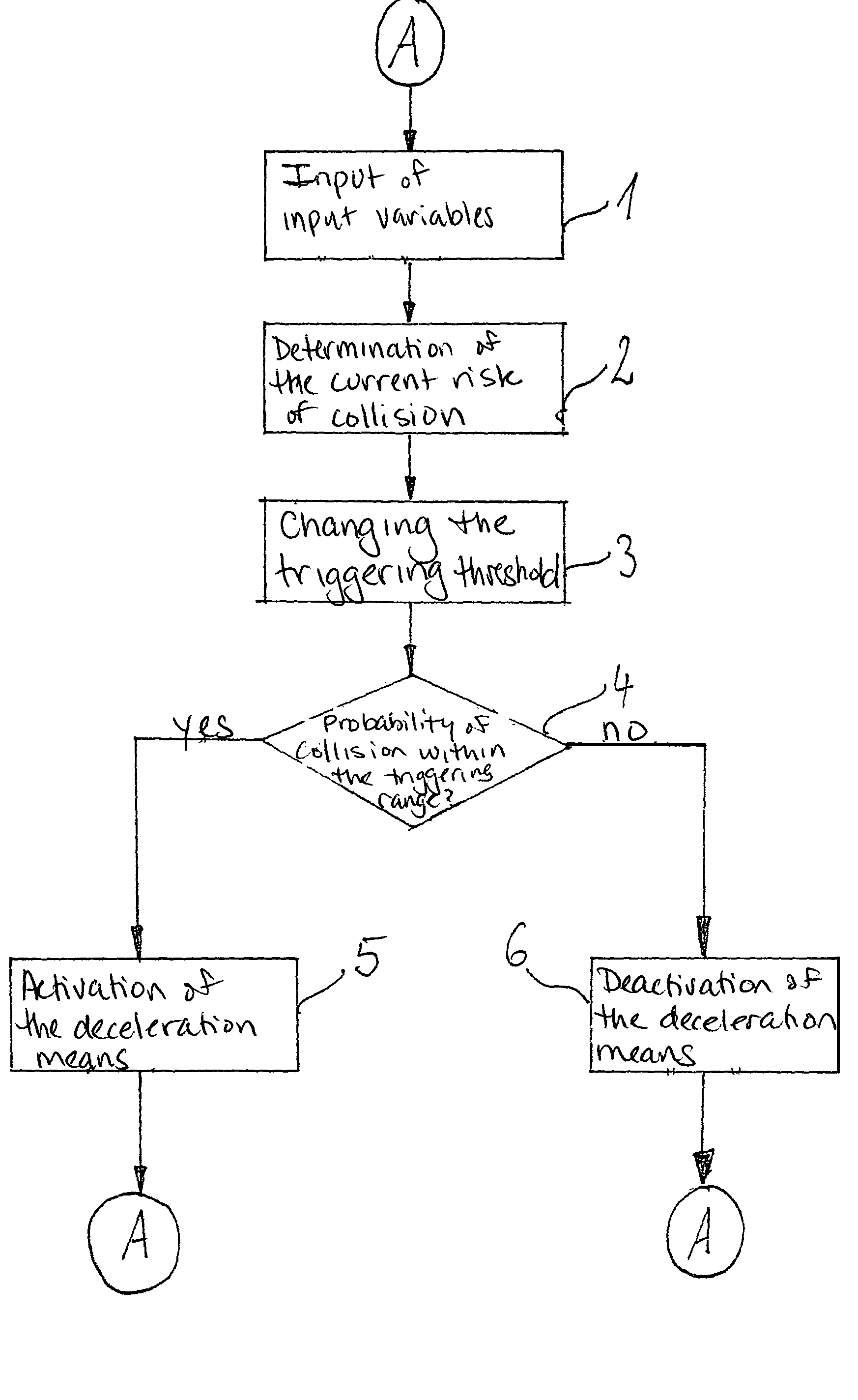
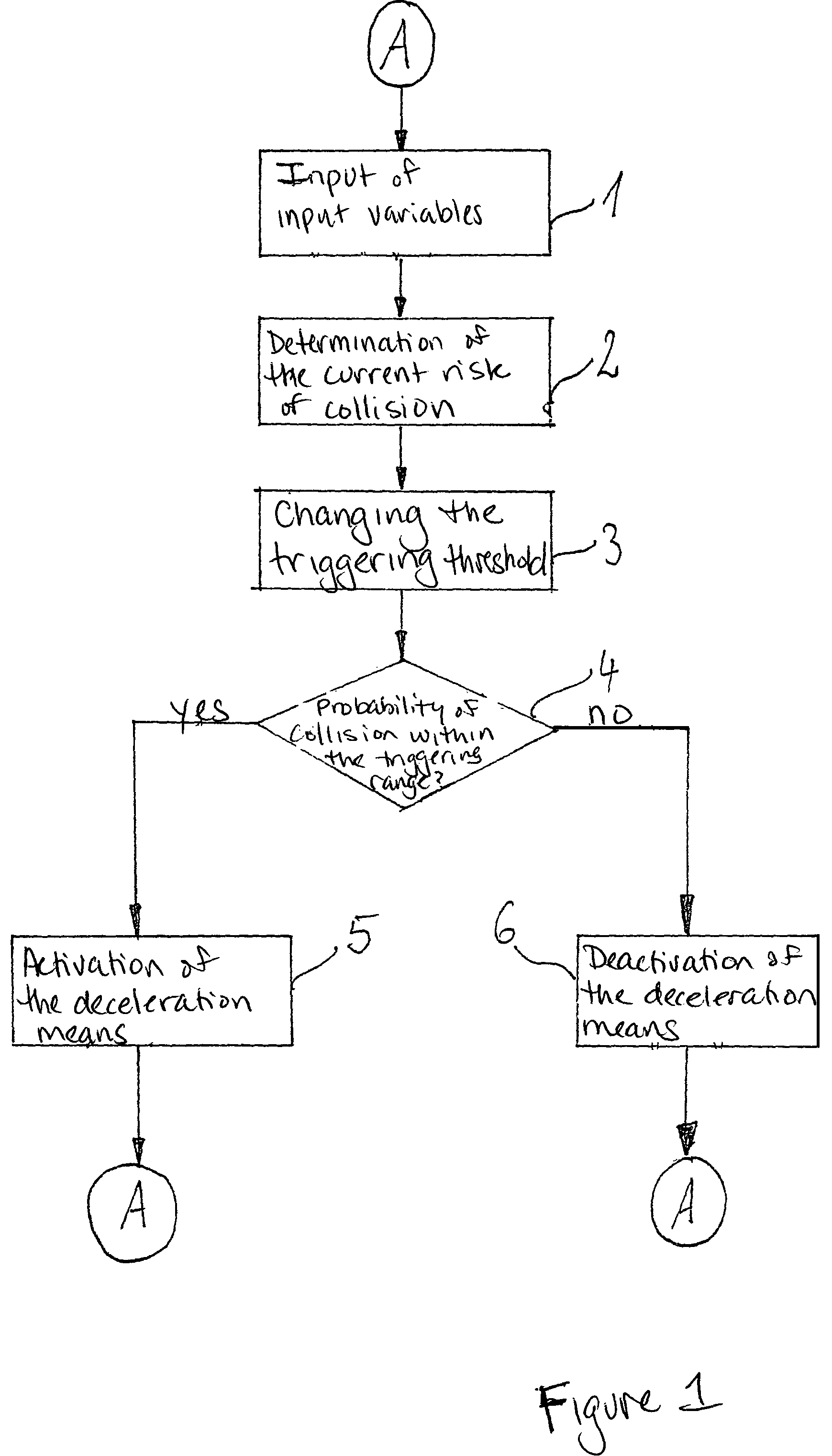
[0032]FIG. 1 shows a flow chart for execution of the exemplary method according to the present invention. At the beginning of the cycle indicated here, which is carried out continuously, the input variables are entered as shown in block 1. Input variables here include signals coming from a steering angle sensor, a brake pedal sensor, an accelerator pedal sensor, a device for determining the vehicle speed, a device for determining the road surface slope or gradient, a device for determining the yaw rate of the vehicle or a device for determining the float angle of the vehicle or a device for detecting stationary and moving objects in the surroundings of the vehicle. On the basis of this data entered in step 1, the current risk of a collision is determined in subsequent step 2.

[0033]This current risk of collision represents the probability that one's own vehicle will collide with a stationary or moving object which is in the direction of movement of one's own vehicle. This current col...


PUM


Abstract

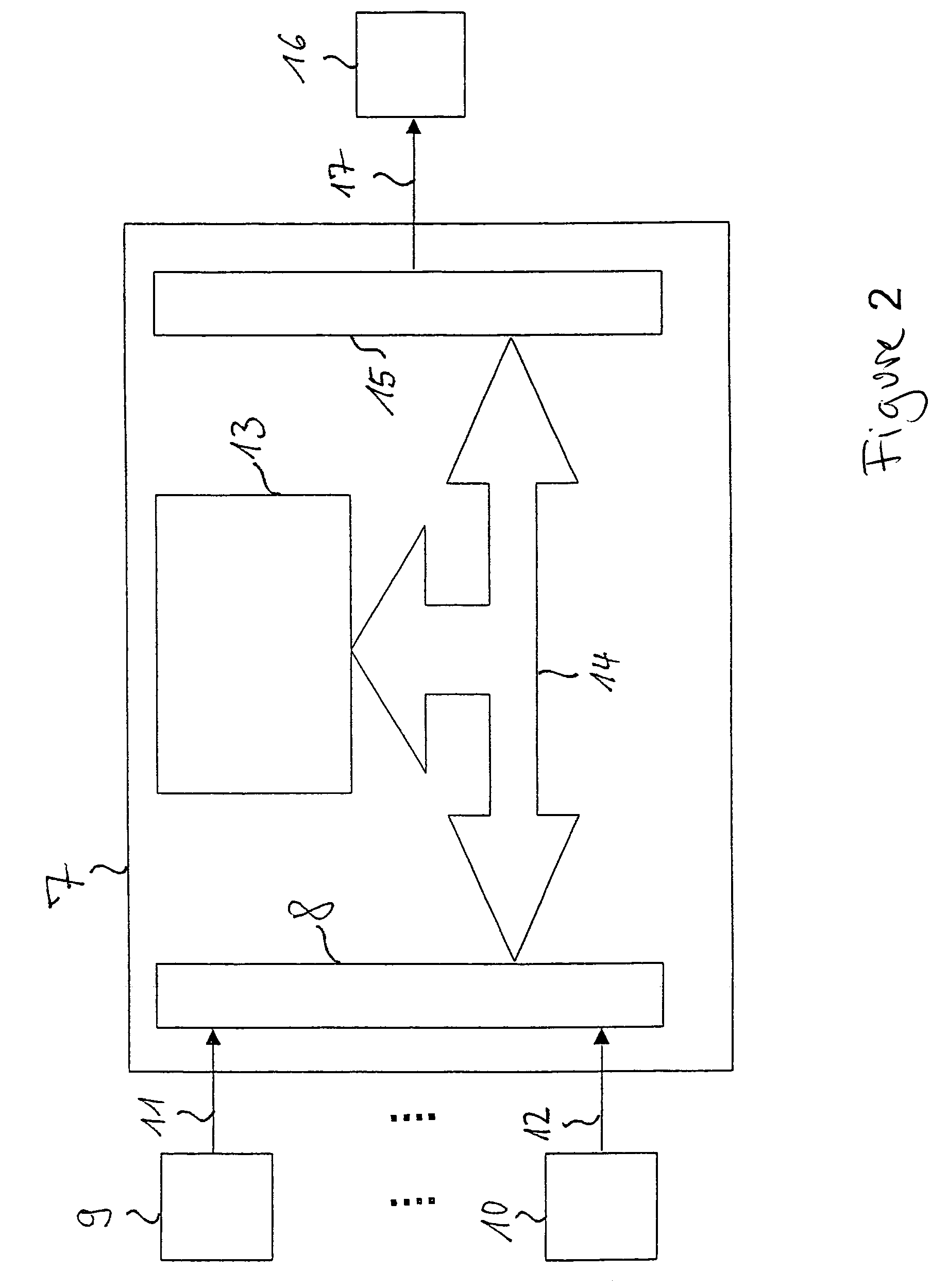
A method and a device for automatic triggering of deceleration of a vehicle for preventing a collision, which is accomplished by the fact that a variable, which represents a probability of collision with another vehicle, must exceed a predefinable threshold value, and the threshold value is variable as a function of the driver's response, the current driving situation, or the ambient situation. To determine the change in the threshold value, signals from a steering angle sensor, a brake pedal sensor, an accelerator pedal sensor, a device for determining the speed of the vehicle, a device for determining the uphill or downhill slope of the road, a device for determining the vehicle yaw rate, a device for determining the vehicle float angle or a device for detecting stationary and moving objects in the vicinity of the vehicle, in particular in the area in front of the vehicle, are analyzed.

Description

RELATED APPLICATION INFORMATION[0001]The present application is a U.S. national phase application of PCT / DE02 / 02547, which was filed on Jul. 11, 2002, and claims priority to and the benefit of German patent application no. 10133027.8, which was filed in Germany on Jul. 11, 2001, the disclosures of all of which are incorporated herein by reference.FIELD OF THE INVENTION[0002]A method and a device for automatic triggering of deceleration of a vehicle to prevent a collision or to reduce the consequences of an imminent collision.BACKGROUND INFORMATION[0003]In the past, there have been systems for providing distance regulation and speed control that expand the functionality of a traditional cruise control to the extent that speed control is switched to distance control when a slower moving vehicle is detected in front of one's own vehicle, and then the vehicle in front is followed at the same speed. The basic functioning of such a distance and speed control system is discussed in the art...

Claims


Application Information

Patent Timeline
Patent Type & Authority Patents(United States)
IPC IPC(8): B60K31/00G06F19/00B60T7/04B60R21/00B60T7/12B60T7/22B60W30/16F02D29/02G08G1/16
CPCB60T7/042B60T7/22B60W30/16G08G1/16B60T2201/022B60T2201/024B60T2201/12
Inventor KNOOP, MICHAELBRAEUCHLE, GOETZWINNER, HERMANNWEILKES, MICHAELHEINEBRODT, MARTINUHLER, WERNERTHIELE, JOACHIMSTAEMPFLE, MARTINOECHSLE, FREDWILHELM, ULF
Owner ROBERT BOSCH GMBH
Learn More