Eureka AIR delivers breakthrough ideas for toughest innovation challenges, trusted by R&D personnel around the world.

Continuous ink-jet printing device, with improved print quality and autonomy

a technology of inkjet printing and continuous ink, which is applied in the direction of printing, etc., can solve the problems of printing errors, printing defects, and electrical crosstalk between these circuits

Inactive Publication Date: 2013-09-24
MARKEM IMAJE HLDG
View PDF26 Cites 41 Cited by
  • Summary
  • Abstract
  • Description
  • Claims
  • Application Information

AI Technical Summary

Benefits of technology

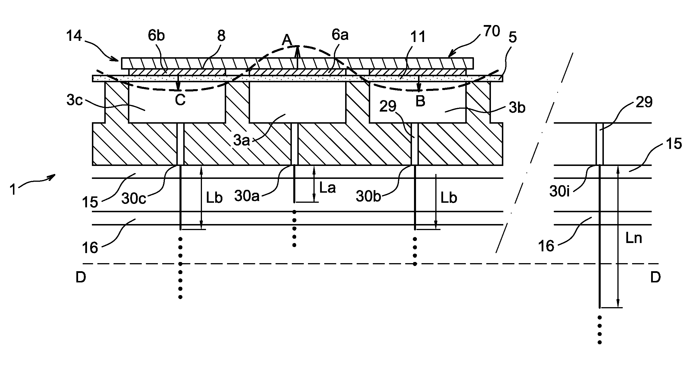
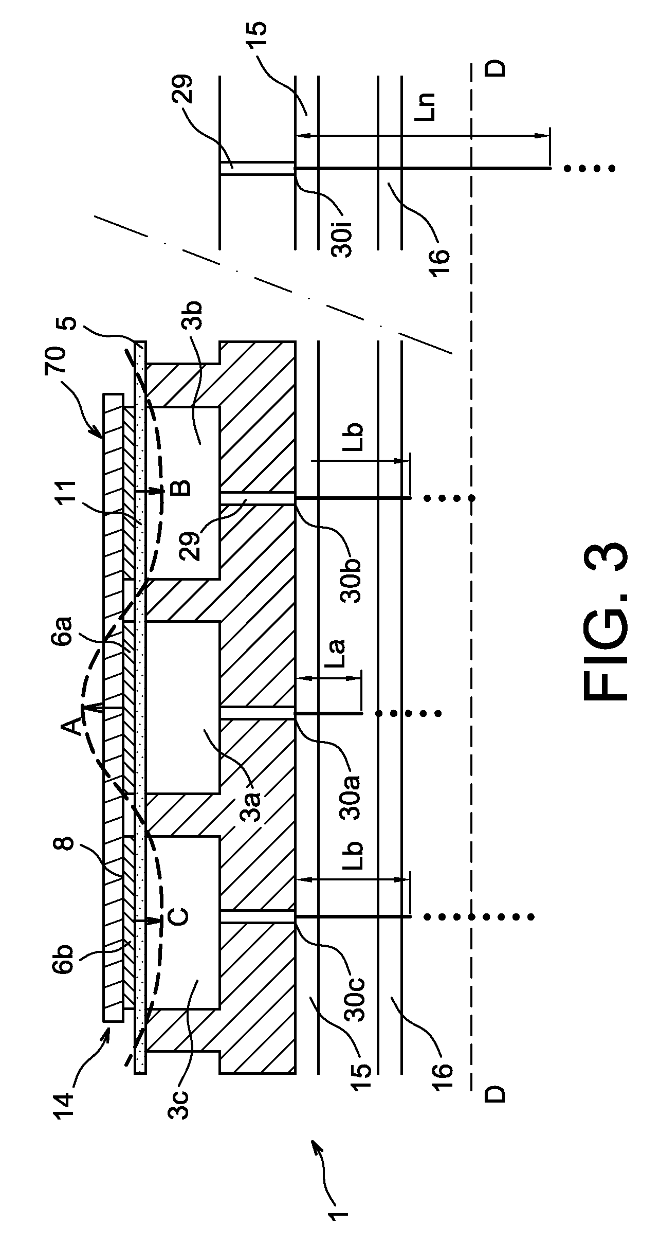
[0059]The invention also relates to a method for reducing the consequences of mechanical crosstalk between adjacent stimulation chambers in the print head of a continuous inkjet printer which includes

Problems solved by technology

This results in electrical crosstalk occurring between these circuits.
This results in printing errors.
It has been observed, however, that after a period of satisfactory operation, printing defects appear.
In the initial stage of the research into the causes of the defects, they were attributed to progressive fouling of the charge and deflection electrodes.
It will be seen later that after research and experimentation the inventors discovered that the problem of fouling of charge or deflection electrodes could result in crosstalk between two adjacent chambers.
These control electronics are complex and are both digital and analogue.
The major drawback of such a step technology is that it does not cancel out crosstalk in real time (that is, at any given moment), irrespective of the shape of the signals applied to the transducers.

Method used


Image

  • Continuous ink-jet printing device, with improved print quality and autonomy
  • Continuous ink-jet printing device, with improved print quality and autonomy
  • Continuous ink-jet printing device, with improved print quality and autonomy

Examples


second embodiment

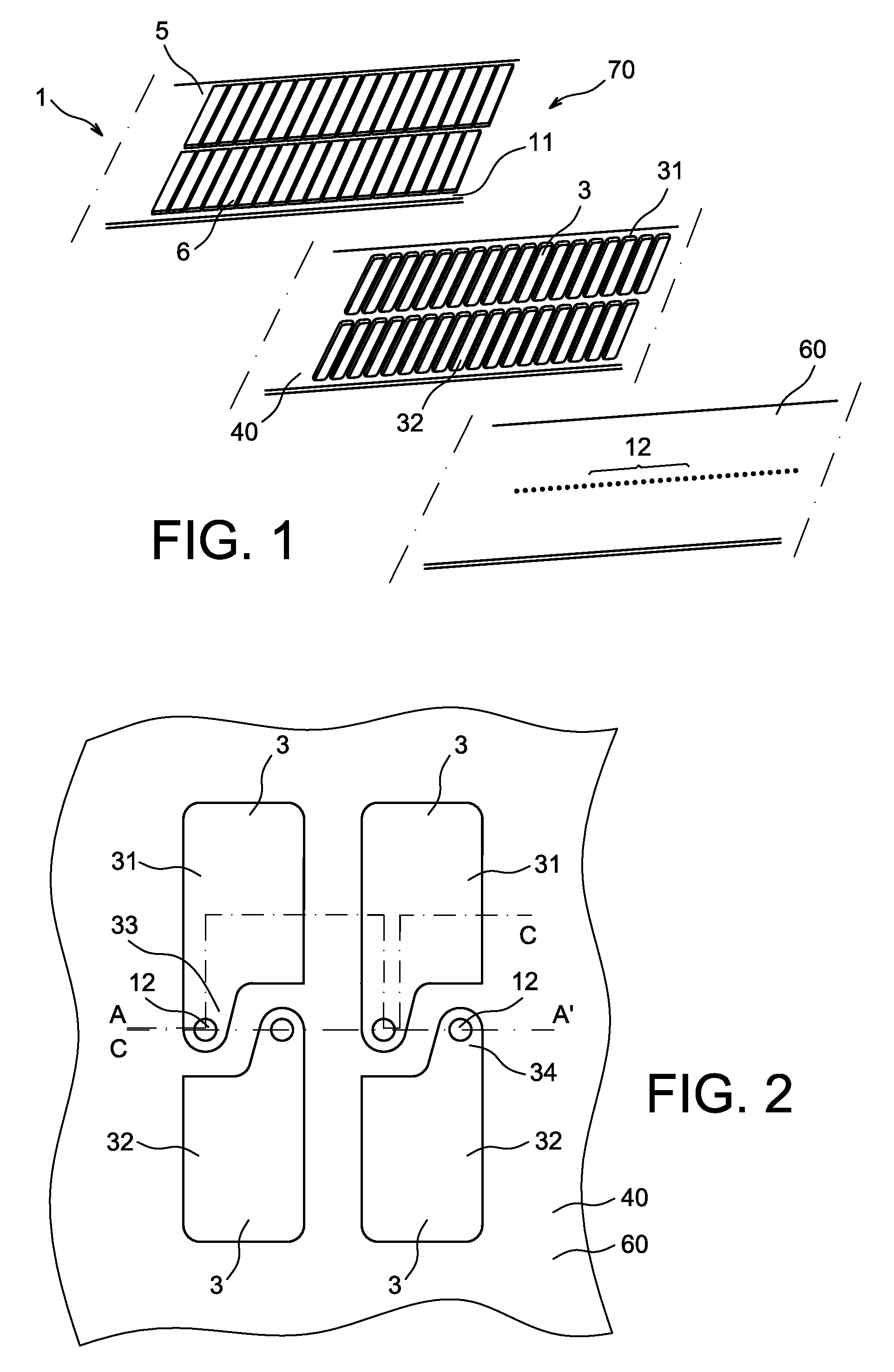
[0101]In an alternative embodiment to those modes shown in FIGS. 6, 8 and 9 the circuit 19 has the form represented in FIG. 7. In this alternative mode the printer is equipped, for example at the device for processing the data to be printed 7, with means for producing and sending stimulation and compensation pulses to the chambers adjacent to the stimulated chamber. Thus, as shown in FIG. 7, simultaneous with sending a stimulation pulse to, for example, actuator 6 supplied by line 92, the device 7 sends to each of the actuators 6 of adjacent chambers supplied by lines 91 and 93, a reduced pulse for compensating for crosstalk. The means for sending pulses may be line coupling components such as those described in connection with FIG. 6, or those which are to be described in connection with FIGS. 8 and 9, but applied to parts of line 9 which are found upstream of the print head, for example, inside the device for processing of the data to be printed 7. It may also involve software mea...

third embodiment

[0103]In a third embodiment, represented in FIG. 9, the lines 9 of actuators of adjacent chambers are coupled two at a time by an assembly of Zener diodes 21, 22 in parallel and have opposite passing directions. Thus when one of the lines receives a pulse, the other receives it but with amplitude which peaks at the diode voltage limit value. Naturally this limiting value is selected so that the V′ / V ratio thus obtained is suitable.

[0104]The graph shown in FIG. 10 represents the variation of the V′ / V ratio as a function of the number of dots per inch (DPI) for a printer which has a diaphragm 5 made of steel with a thickness of 50 μm. The first line of the abscissa axis shows the number of dots per inch and the second line shows the value of the corresponding gap between consecutive nozzles, that is, the approximate value of 25400 μm divided by the number of dots per inch. It can be seen that the ratio V′ / V increases with the number of DPI. The inventors consider it reasonable to envi...


PUM


Abstract

A continuous ink-jet printer or a print head of such a printer which includes electrical means for compensating for mechanical crosstalk between adjacent stimulation chambers, where these means simultaneously with the transmission, to a stimulated chamber, of a stimulation pulse on a stimulation line send a pulse for compensating for mechanical crosstalk on each of the lines supplying an actuator for the chamber adjacent to the stimulated chamber. Specific ratios between the peak amplitude of pulse for compensating for crosstalk and the peak voltage value of the stimulation pulse are provided as a function of the gaps between consecutive nozzles.

Description

[0001]This application is a 371 of PCT Application No. PCT / EP2010 / 067937 filed Nov. 22, 2010, which claims the priority benefit of U.S. Provisional Application No. 61 / 290,321 filed Dec. 28, 2009.TECHNICAL FIELD[0002]The invention relates to the field of continuous ink-jet printers with a multi-nozzle print head.[0003]It also relates to the print head of such printers.PRIOR ART[0004]Multi-nozzle continuous ink-jet printers include a print head. This head includes an ink drop generator, one or more drop charge electrodes and one or more drop deflection electrodes. The ink drop generator includes in particular one or more ink supply conduits, stimulation chambers which are hydraulically connected with ink jet discharge nozzles. In addition the generator includes means for stimulation and one or more gutters for recovering ink ejected by the discharge nozzles and which is not used for printing. The ink arrives under pressure through ink supply conduits until it is inside the stimulation...

Claims


Application Information

Patent Timeline
Patent Type & Authority Patents(United States)
IPC IPC(8): B41J2/02
CPCB41J2/03B41J2002/022
Inventor BARBET, BRUNO
Owner MARKEM IMAJE HLDG
Why Eureka
Eureka Blog
Learn More