Start flow measurement

a technology of start flow and measurement, which is applied in the direction of engine control, hot gas positive displacement engine plants, lighting and heating apparatus, etc., can solve the problems of pump life and flow accuracy

Active Publication Date: 2010-11-30
PRATT & WHITNEY CANADA CORP
View PDF37 Cites 6 Cited by
  • Summary
  • Abstract
  • Description
  • Claims
  • Application Information

AI Technical Summary

Problems solved by technology

Controlling the start fuel flow with the metering valve / pump may lead to flow accuracy problems, given the factor that the fuel flow is in a very small amount in contrast to the maximum fuel flow to be pumped by the demand fuel pump, and that pump wear over the life of the pump could lead to problems with metering the start fuel flows.

Method used


Image

  • Start flow measurement
  • Start flow measurement
  • Start flow measurement

Examples


Embodiment Construction

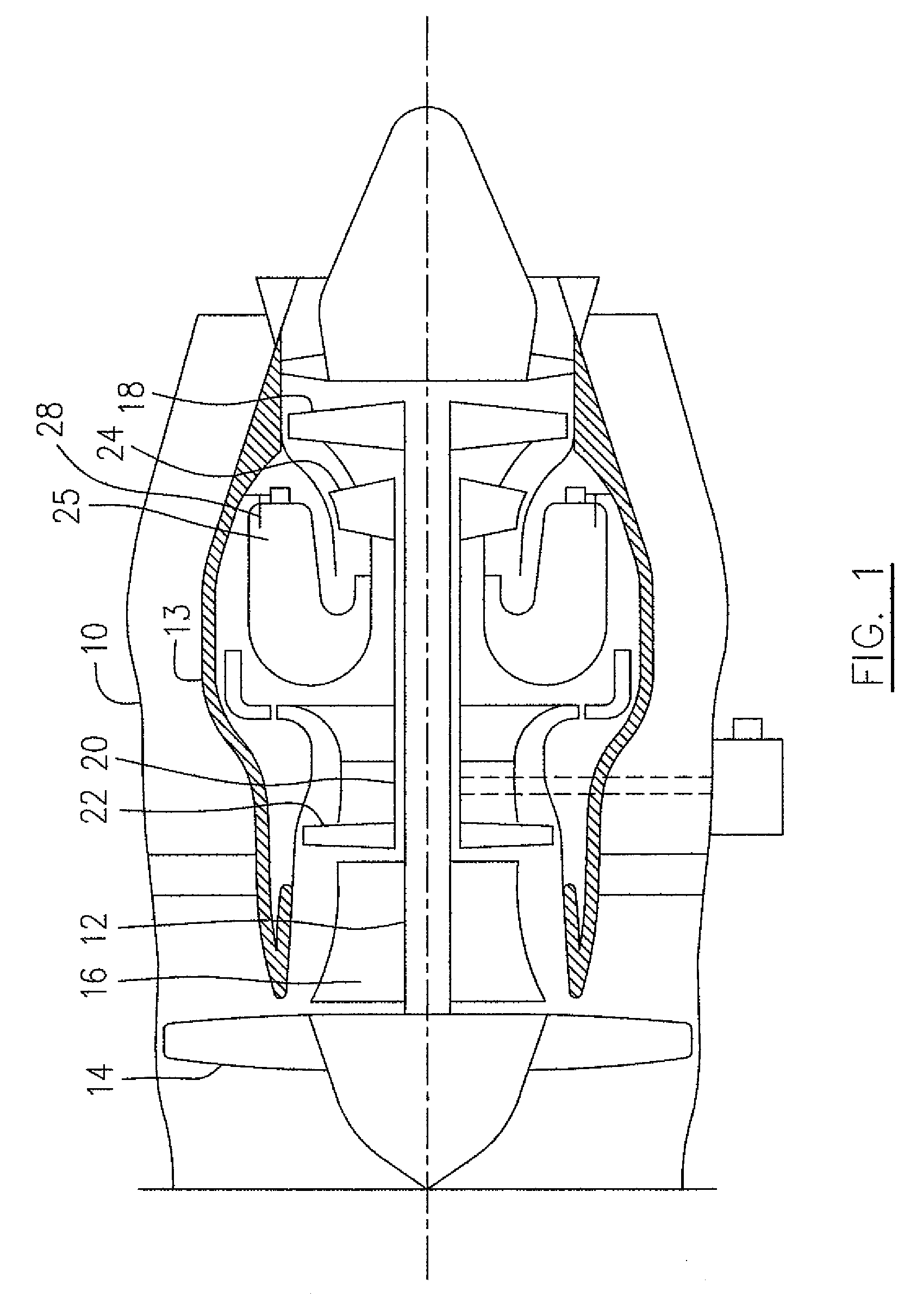
[0013]Referring to FIG. 1, a turbofan gas turbine engine incorporating an embodiment of the present approach includes a bypass duct 10, a core casing 13, a low pressure spool assembly seen generally at 12 which includes a fan assembly 14, a low pressure compressor assembly 16 and a low pressure turbine assembly 18, and a high pressure spool assembly seen generally at 20 which includes a high pressure compressor assembly 22 and a high pressure turbine assembly 24. The core casing 13 surrounds the low and high pressure spool assemblies 12 and 20 in order to define a main fluid path (not indicated) therethrough. In the main fluid path there are provided a combustor seen generally at 25 and a fuel system 28, including fuel nozzles (not depicted in FIG. 1) for delivery of fuel to the combustor 25 for combustion. The compressor assemblies 16 and 22 provide a compressed airflow (not indicated) through the main fluid path and in communication with the combustor 25 for combustion therein.

[00...


PUM


Abstract

A method and apparatus for measuring a start fuel flow to a pilot nozzle of a fuel system of a gas turbine engine using pressure differential between fuel passages leading to fuel nozzles.

Description

TECHNICAL FIELD[0001]The invention relates generally to gas turbine engines and more particularly, to an improved fuel system for gas turbine engines.BACKGROUND OF THE ART[0002]During a gas turbine engine starting, fuel is first provided to primary fuel nozzles which function as pilot nozzles, in order to deliver a very small amount of fuel near to the igniter system in the combustor for ignition at these nozzles to produce pilot torches in the combustor. Fuel is then provided to a set of main fuel nozzles, often through a manifold, to deliver the fuel at a relatively higher fuel pressure and high flow rate to start and maintain the continuous combustion in the combustor. The start flow needs to be accurately delivered and is normally metered by a metering valve / pump in demand fuel pumping systems. Controlling the start fuel flow with the metering valve / pump may lead to flow accuracy problems, given the factor that the fuel flow is in a very small amount in contrast to the maximum f...

Claims


Application Information

Patent Timeline
Patent Type & Authority Patents(United States)
IPC IPC(8): F02C7/22F02C7/26
CPCF02C7/222F02C7/232F02C7/26F02C9/26F23N5/184F23R3/343F23N2005/185F23N2025/06F23N2027/10F23N2037/02F05D2270/3015F23N2225/06F23N2227/10F23N2237/02
Inventor DOOLEY, KEVIN ALLAN
Owner PRATT & WHITNEY CANADA CORP
Why Eureka
Try Eureka