
Water control valve

a control valve and water control technology, applied in the field of water control valves, can solve the problems of inconvenient use, complex and crude appearance of conventional knob-operated water control valves, and conventional knob-operated valves that do not appeal to the taste of modern people, and achieve the effect of reducing the amount of needlessly consumed water, facilitating and quickly manipulating, and quickly controlling

Inactive Publication Date: 2010-11-30
KIM JONG KOO
View PDF2 Cites 21 Cited by
  • Summary
  • Abstract
  • Description
  • Claims
  • Application Information

AI Technical Summary

Benefits of technology

Enables quick and precise control of water temperature and flow rate, reducing unnecessary water consumption and minimizing the risk of operational malfunctions by allowing independent manipulation of control levers without affecting existing flow rates or temperatures.

Problems solved by technology

However, when it is desired to use mixed water of a desired temperature, the cold water knob and the hot water knob must be carefully manipulated to provide the desired temperature, resulting in inconvenience to users.
Due to the plurality of valve cartridges having many elements, the conventional knob-operated water control valve has a complex and crude appearance.
Thus, the conventional knob-operated valve does not appeal to the taste of modern people preferring a simple and refined appearance to a complex and crude appearance.
Furthermore, due to the provision of the plurality of valve cartridges in a knob-operated valve, production costs of the valve are increased.
The conventional lever-operated water control valves are problematic in that they needlessly waste an excessive amount of water because the lever-operated valves cannot precisely control the flow rate of water.
Most conventional lever-operated water control valves are designed as single lever-type valves each having one lever, inducing a manipulation problem in which the valves may change the existing flow rate of water during a temperature control operation and change the existing temperature of water during a flow rate control operation.
Therefore, the conventional lever-operated water control valves having single lever have the above-mentioned manipulation problem.
Furthermore, in the operation of the conventional lever-operated water control valves having the single lever, the lever cannot be precisely manipulated, so that excessive time is required to control the temperature of water to a desired point during which an excessive amount of water is discharged from the valve and is needlessly wasted.
In addition, the users of the lever-operated water control valves unintentionally fully open the valves, thereby wasting an excessive amount of water.

Method used


Image

  • Water control valve
  • Water control valve
  • Water control valve

Examples


first embodiment

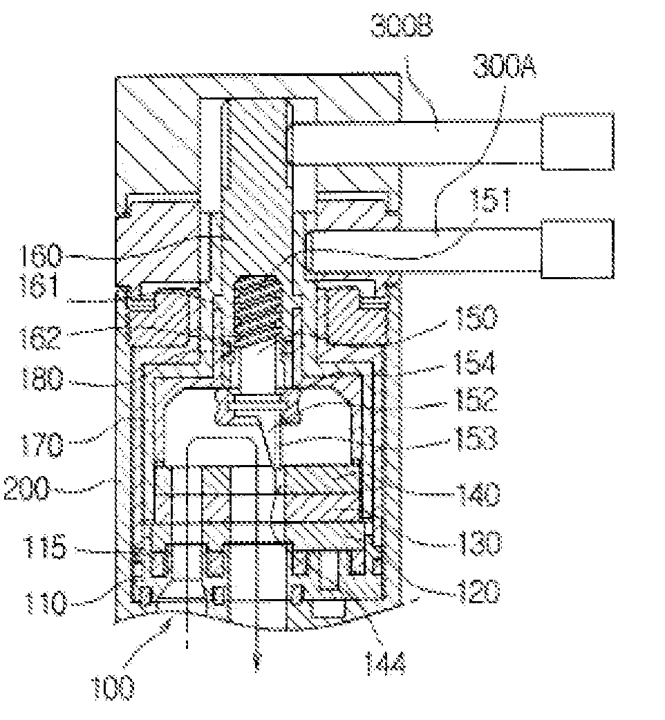
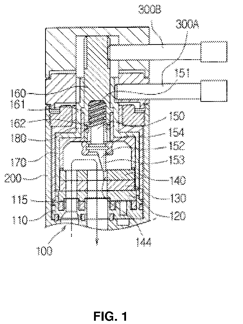
[0044]FIG. 1 is a sectional view of a water control valve according to the present invention. FIG. 2 is an exploded perspective view illustrating in detail the construction of a valve cartridge included in the water control valve. FIG. 3 is an exploded perspective view illustrating in detail the construction of both a temperature control part, stop bushing and a flow rate control part, included in the water control valve, according to the present invention.

[0045]As shown in FIGS. 1 through 3, the water control valve according to the present invention comprises a first fixed disk 120 to guide hot and cold water flowing from outside water pipes (not shown) into a valve cartridge 100, a second fixed disk 140 to guide the hot water, cold water or a mix of hot and cold water in the valve cartridge 100, and a rotary disk 130 interposed between the two fixed disks 120 and 140 such that the rotary disk 130 is in surface contact with the two fixed disks 120 and 140 and controls the temperatu...

second embodiment

[0053]Described in detail, in the valve a plurality of longitudinal holes 157 is formed around the sidewall of the moving unit 150. Furthermore, an axial path is formed through the moving unit 150 at the end thereof opposite the second fixed disk 140, while an outlet hole 164 is axially formed through the flow rate control unit 160 and communicates with the axial path of the moving unit 150.

[0054]During operation of the valve according to the second embodiment, inlet water from the water passage hole 141 of the second fixed disk 140 passes through the longitudinal holes 157 of the moving unit 150, and is discharged from the valve cartridge 100 to the end of the valve opposite the cartridge base block 110 through the outlet hole 164 of the flow rate control unit 160.

[0055]In the second embodiment, to stop water flowing from the water discharge holes 123, 132 and 142 of the disks 120, 130 and 140, the water discharge hole of a valve body 200 is closed.

[0056]In the drawings, the refer...


PUM


Abstract

A water control valve, which has one valve cartridge to control the temperature and flow rate of hot water, cold water or a mix of hot and cold water only through rotating motions, is disclosed. The valve cartridge (100) has a first fixed disk (120) to guide hot and cold water into the valve cartridge, a rotary disk (130) to control the flow rate of hot and cold water from the first fixed disk, thus controlling the temperature of water, a second fixed disk (140) to guide controlled water in the cartridge, a temperature control unit (170) to rotate the rotary disk during rotation of a temperature control lever, the moving unit (150) to linearly move toward or away from the second fixed disk, thus controlling the flow rate of discharged water, and a flow rate control unit (160) to cause linear movement of the moving unit by rotation.

Description

REFERENCE TO RELATED APPLICATIONS[0001]This is a continuation of pending International Patent Application PCT / KR2005 / 002131 filed on Jul. 5, 2005, which designates the United States and claims priority of Korean Patent Application No.10-2004-0115142 filed on Dec. 29, 2004.FIELD OF THE INVENTION[0002]The present invention relates, in general, to water control valves, which are called “faucets” in the related art, and, more particularly, to a water control valve which controls the temperature of water by mixing hot and cold water and controls the flow rate of the hot water, cold water or a mix of hot and cold water only through rotating motions, and has both a temperature control lever and a flow rate control lever provided at a side of a valve body, thus allowing a user to easily manipulate the two control levers to precise angles, and in which the two control levers do not interfere with each other during operation so that the valve changes neither the existing flow rate of water du...

Claims


Application Information

Patent Timeline
Patent Type & Authority Patents(United States)
IPC IPC(8): F16K11/072
CPCF16K3/32F16K11/074F16K31/508Y10T137/87096Y10T137/86549Y10T137/87129Y10T137/86863Y10T137/7668F16K3/314F16K27/04
Inventor KIM, JONG KOO
Owner KIM JONG KOO
Learn More