Hydro-electric hybrid drive system for motor vehicle

a hybrid drive and hybrid technology, applied in the direction of machines/engines, electric devices, jet propulsion mounting, etc., can solve the problems of inability to meet the widespread use of known systems, lack of flexibility in their operation, and inefficient use of known systems energy, so as to achieve greater fuel economy and emissions, wide ratio span, and improved fuel economy

Inactive Publication Date: 2010-11-30
BOSCH REXROTH AG
View PDF48 Cites 70 Cited by
  • Summary
  • Abstract
  • Description
  • Claims
  • Application Information

AI Technical Summary

Benefits of technology

[0012]The hybrid electro-hydraulic drive system in accordance with the present invention provides a number of advantages over the current hydraulic or electric regenerative drive systems of equivalent performance levels.

Problems solved by technology

The current systems have however lacked flexibility in their operation, as they principally have been arranged to dump accumulated energy all at once, for example when a vehicle is accelerating from a standing start, while those systems that have allowed for more controlled release of stored energy, have not done so to optimum efficiency.
The use of the energy in the known systems is therefore somewhat inefficient and the known systems therefore have not met with widespread use.
Additionally, known systems are time consuming and labor intensive to install.
Due to the reduction gear ratio of the vehicular transmission and the inherent frictional and other power losses in the transmission, the motor / pump unit of the current hybrid hydraulic drive systems should generate substantial amount of the pressurized hydraulic fluid.
Single speed driveline integrated systems are limited in their maximum power contribution by the speed of the driveline.
Typically when the vehicle speed is low, the driveline speeds are low, this results in low power availability to the driveline.
For a single speed driveline integrated design, the power availability differential can only be partially mitigated through the use of a larger pump / motor.
At some point, depending on the particular application, it becomes unreasonable to increase the size of the pump / motor.
This lower maximum operating speed often reduces the operation range of the entire hybrid hydraulic system and thus reduces system effectiveness.
However, the additional cost, complexity and weight of such multi-speed designs detract from the feasibility of multi-speed designs.
Ultimately the functionality of such multi-speed interface systems duplicates the functionality of the vehicle transmission and is therefore redundant.
Therefore, the motor / pump unit of the current driveline integrated hybrid hydraulic drive systems is relatively large in size, heavy and bulky.

Method used


Image

  • Hydro-electric hybrid drive system for motor vehicle
  • Hydro-electric hybrid drive system for motor vehicle
  • Hydro-electric hybrid drive system for motor vehicle

Examples


Embodiment Construction

[0034]The preferred embodiments of the present invention will now be described with the reference to accompanying drawings.

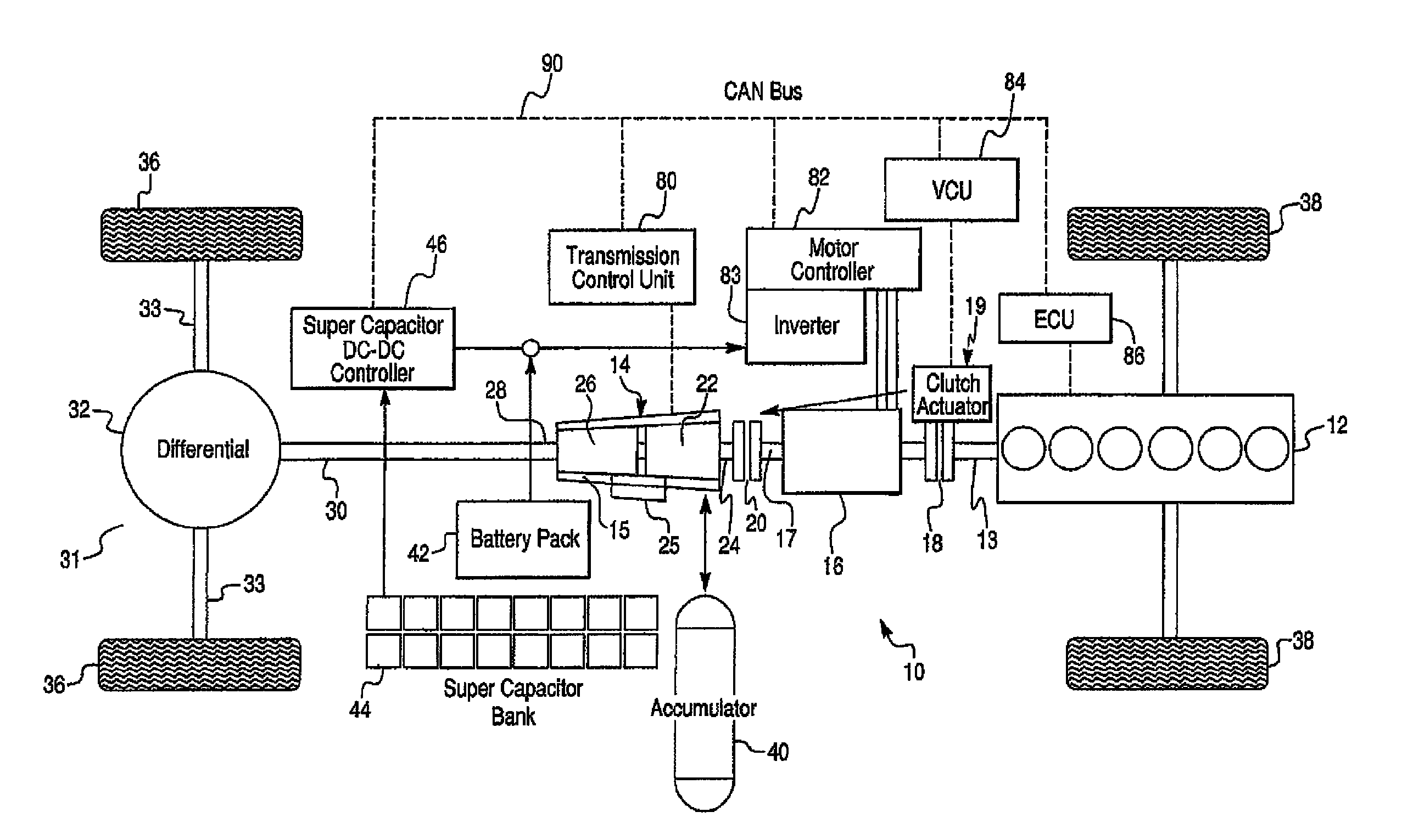
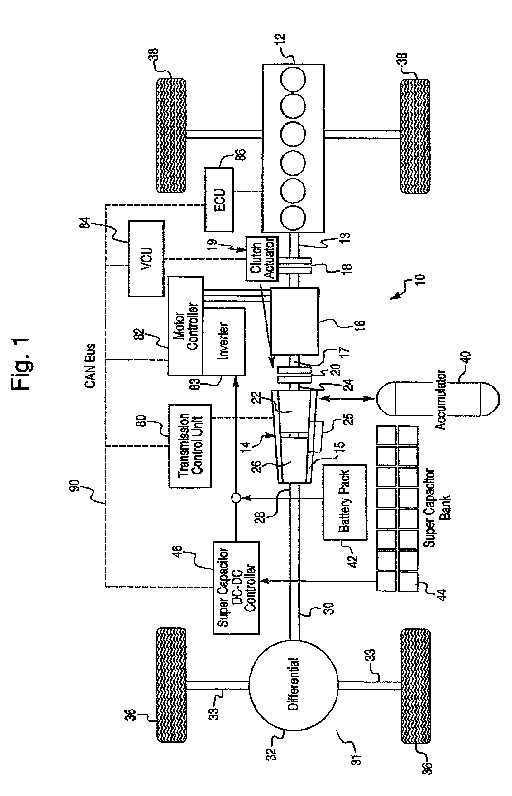
[0035]FIG. 1 schematically depicts a hydroelectric hybrid drive system 10 in accordance with a first exemplary embodiment of the present invention for application in a motor vehicle. The hybrid drive system 10 comprises a prime mover, such as an internal combustion engine (IC engine) 12, a hydraulic transmission 14, and an electric motor / generator (M / G) 16 interposed between the IC engine 12 and the hydraulic transmission 14. In other words, the hydraulic transmission 14 and the electric motor / generator 16 are connected to the internal combustion engine 12 in series. Preferably, the hydraulic transmission 14 is an infinitely variable hydrostatic transmission (IVT) including a first hydraulic machine 22 having an input shaft 24, and a second hydraulic machine 26 having an output shaft 28. The first and second hydraulic machines 22 and 26 are hydraulically connect...


PUM


Abstract

A hybrid electro-hydraulic drive system is provided for a vehicle and comprises a hydraulic transmission including a first hydraulic machine and at least one second hydraulic machine drivingly connected to drive wheels of the motor vehicle for driving thereof, an electric motor / generator operatively connected to the first hydraulic machine, and at least one energy storage device operable to store and release a hydraulic fluid energy or an electrical energy. The second hydraulic machine is a reversible hydraulic pump / motor unit capable to function both as a hydraulic pump and a hydraulic motor. The energy storage device is operatively connected to either the hydraulic transmission or the electric motor / generator. In a retarding mode the hydraulic transmission and / or the electric motor / generator retard the vehicle, while in a driving mode they supply a supplementary power to the drive wheels to assist propulsion of the vehicle.

Description

CROSS REFERENCE TO RELATED APPLICATIONS[0001]This application relates to and claims priority under 35 U.S.C. 119(e) of U.S. Provisional Patent Application Ser. No. 60 / 629,560 filed on Nov. 22, 2004; U.S. Provisional Patent Application Ser. No. 60 / 629,561 filed on Nov. 22, 2004; and U.S. Provisional Patent Application Ser. No. 60 / 629,562 filed on Nov. 22, 2004, which are incorporated herein by reference.BACKGROUND OF THE INVENTION[0002]1. Field of the Invention[0003]The present invention relates to hybrid drive systems in general and, more particularly, to a hybrid drive system of a motor vehicle including a combination of a hydraulic transmission and an electric drive.[0004]2. Description of the Prior Art[0005]Hybrid hydraulic (or regenerative) drive systems are known and have been applied to motor vehicles, especially trucks and buses. Such systems harness energy by retarding the vehicle under braking conditions and accumulating that energy for later use to propel the vehicle. More...

Claims


Application Information

Patent Timeline
Patent Type & Authority Patents(United States)
IPC IPC(8): B60K6/20
CPCB60K6/12B60K6/32B60K6/48B60K6/485B60K6/52F03C1/0403F03C1/0447F04B17/05B60K17/356Y02T10/6208Y02T10/6221Y02T10/6226Y02T10/6265Y02T10/6282Y02T90/34F02N7/00B60L15/2054B60L2220/42B60L2240/486B60L2240/507B60L2260/28B60L2220/50Y02T10/70Y02T10/72B60L50/40B60L50/16Y02T10/62Y02T10/64Y02T10/7072Y02T90/40
Inventor LYNN, ALFRED EDMUNDROSE, KENRICBASELEY, SIMON JOHNDUGGAN, JAMES A
Owner BOSCH REXROTH AG
Why Eureka
Try Eureka