Hybrid hydraulic drive system with engine integrated hydraulic machine

a hybrid hydraulic drive and hydraulic machine technology, applied in mechanical equipment, propulsion parts, transportation and packaging, etc., can solve the problems of inability to meet the needs of widespread use, lack of flexibility in the operation of current systems, and inefficient use of energy in known systems, so as to achieve equal performance levels, reduce fuel consumption, and power contribution

Inactive Publication Date: 2007-09-25
BOSCH REXROTH AG
View PDF36 Cites 146 Cited by
  • Summary
  • Abstract
  • Description
  • Claims
  • Application Information

AI Technical Summary

Benefits of technology

[0015]The hybrid hydraulic drive system in accordance with the present invention provides a number of advantages over the current hydraulic regenerative drive systems of equivalent performance levels, such as size and weight reduction, lower cost, allows for operation over a wider vehicle operating speed range, allows for some hydraulic pump / motor functionalities even with the stationary vehicle, better adaptability for the existing vehicular chassis, etc.

Problems solved by technology

The current systems have however lacked flexibility in their operation, as they principally have been arranged to dump accumulated energy all at once, for example when a vehicle is accelerating from a standing start, while those systems that have allowed for more controlled release of stored energy, have not done so to optimum efficiency.
The use of the energy in the known systems is therefore somewhat inefficient and the known systems therefore have not met with widespread use.
Additionally, known systems are time consuming and labor intensive to install.
Due to the reduction gear ratio of the vehicular transmission and the inherent frictional and other power losses in the transmission, the motor / pump unit of the current hybrid hydraulic drive systems should generate substantial amount of the pressurized hydraulic fluid.
Single speed driveline integrated systems are limited in their maximum power contribution by the speed of the driveline.
Typically when the vehicle speed is low, the driveline speeds are low, this results in low power availability to the driveline.
For a single speed driveline integrated design, the power availability differential can only be partially mitigated through the use of a larger pump / motor.
At some point, depending on the particular application, it becomes unreasonable to increase the size of the pump / motor.
This lower maximum operating speed often reduces the operation range of the entire hybrid hydraulic system and thus reduces system effectiveness.
However, the additional cost, complexity and weight of such multi-speed designs detract from the feasibility of multi-speed designs.
Ultimately the functionality of such multi-speed interface systems duplicates the functionality of the vehicle transmission and is therefore redundant.
Therefore, he motor / pump unit of the current driveline integrated hybrid hydraulic drive systems are relatively large in size, heavy and bulky.
This required structure will often present a challenge in and of itself to design, and fit into the vehicle chassis.
Furthermore, in some vehicles equipped with all-wheel drive, where the power delivered to the driveline from the transmission is split via a transfer case between the front and rear axles via a differential gear set, there may also be torque management issues to address.
When power is added to one side of the driveline, the possibility exists for serious torque management issues that could cause loss of vehicle control.

Method used


Image

  • Hybrid hydraulic drive system with engine integrated hydraulic machine
  • Hybrid hydraulic drive system with engine integrated hydraulic machine
  • Hybrid hydraulic drive system with engine integrated hydraulic machine

Examples


Embodiment Construction

[0020]The preferred embodiment of the present invention will now be described with the reference to accompanying drawings.

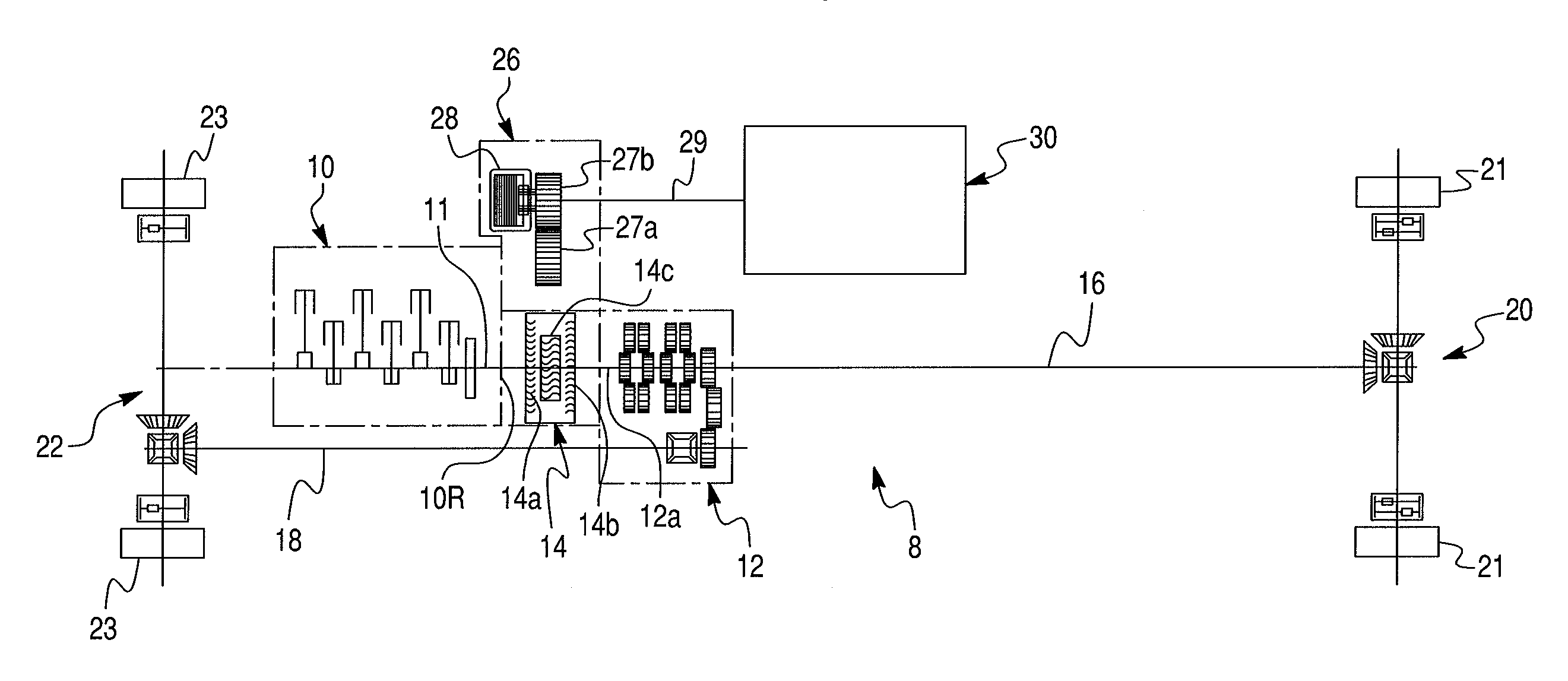
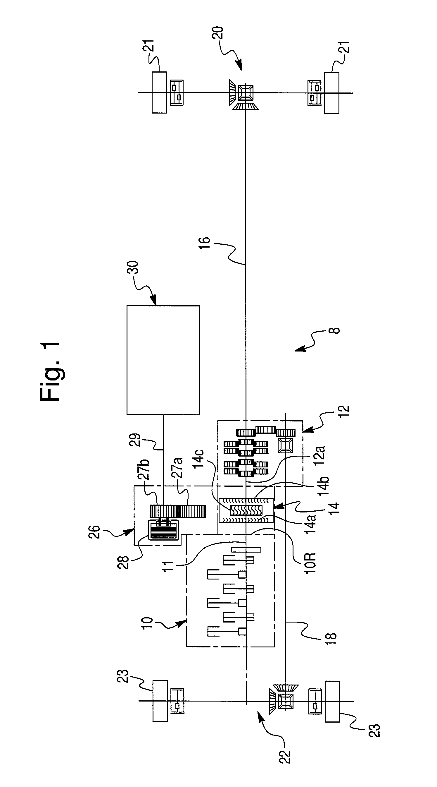
[0021]FIG. 1 schematically depicts a hybrid hydraulic (or regenerative) drive system 8 in accordance with a first embodiment of the present invention for application in motor vehicles, especially heavy land vehicles, such as trucks and buses. The hybrid drive system 8 comprises a prime mover 10, such as an internal combustion engine or electric motor, and a vehicular multi-speed transmission 12. Preferably, the transmission 12 is a planetary automatic transmission including a hydrodynamic torque converter 14 that drivingly couples the prime mover 10 to the transmission 12. It will be appreciated that any appropriate type of vehicular transmission is within the scope of the present invention. In turn, the torque converter 14 includes a turbine 14a (or pump) non-rotatably coupled to an output shaft 11 of the prime mover 10, an impeller 14b non-rotatably coupled to ...


PUM


Abstract

A hybrid hydraulic drive system for a vehicle comprises a prime mover, a transmission connecting the prime mover to drive wheels, a fluid energy storage accumulator, and a reversible hydraulic machine in fluid communication with the energy storage accumulator and drivingly coupled to the prime mover upstream of the transmission. The hybrid hydraulic drive system is arranged such that in a retarding mode the reversible hydraulic machine retards the drive wheels of the vehicle by pumping fluid into the accumulator. In a driving mode the reversible hydraulic machine supplies a supplementary power to the drive wheels of the vehicle using the pressurized fluid from the accumulator to assist propulsion of the vehicle. In a neutral mode the reversible hydraulic machine is disconnected from the prime mover to render the reversible hydraulic machine substantially inoperative to exert any significant driving or retarding influence on the drive wheels.

Description

BACKGROUND OF THE INVENTION[0001]1. Field of the Invention[0002]The present invention relates to hybrid hydraulic drive systems in general and, more particularly, to a hydraulic drive system of a motor vehicle generating and accumulating propulsion energy by retardation of movement, including an integrated hydraulic machine operatively coupled to a prime mover upstream of a vehicular transmission[0003]2. Description of the Prior Art[0004]Hybrid hydraulic (or regenerative) drive systems are known and have been applied to motor vehicles, especially trucks and buses. Such systems harness energy by retarding the vehicle under braking conditions and accumulating that energy for later use to propel the vehicle. More specifically, typical hybrid hydraulic drive systems utilize a hydraulic machine in the form of an integrated hydraulic pump / motor unit to absorb and add power to a conventional vehicle drive system. While the system is absorbing power the hydraulic pump / motor unit is used to ...

Claims


Application Information

Patent Timeline
Patent Type & Authority Patents(United States)
IPC IPC(8): B60K6/12
CPCB60K6/12Y10T477/60Y02T10/6208Y02T10/62B60K2006/268
Inventor ROSE, KENRIC B.
Owner BOSCH REXROTH AG
Why Eureka
Try Eureka