Electric metal tube push-in fitting

a technology of push-in fittings and metal tubes, which is applied in the direction of fluid pressure sealing joints, couplings, mechanical instruments, etc., can solve the problems of not being cost effective and/or practical for their intended purpose, known connectors or fittings are relatively complex, and known connectors or fittings are not suitable for use with electrical metal conduits or tubes

Active Publication Date: 2010-11-30
BRIDGEPORT FITTINGS LLC
View PDF32 Cites 81 Cited by
  • Summary
  • Abstract
  • Description
  • Claims
  • Application Information

AI Technical Summary

Benefits of technology

[0013]In one form of the invention, the intermediate planar portion of the locking device is provided with one or more holding tangs blanked or cut out of the plane of the intermediate planar portion that are outwardly bent and arranged to be received in a corresponding tang opening formed in the connector body adjacent the inlet opening in a manner to prohibit any pull-out of the locking device from the connector body.
[0014]A resilient circular sealing ring or washer may be optionally seated within the intermediate chamber immediately forward of the leading edge of the locking ring. The arrangement is such that to effect the connection of an electric metal tube to the connector body, one need only push one end of the electric metal tube through the inlet opening and through the locking or gripping tangs of the locking device.

Problems solved by technology

Generally, the known connectors or fittings are relatively complex.
Many consist of a relatively large number of component parts that require assembly which may not be cost effective and / or practical for their intended purpose.
Further, some of the known connectors or fittings are not suitable for use with electrical metal conduits or tubes.

Method used


Image

  • Electric metal tube push-in fitting
  • Electric metal tube push-in fitting
  • Electric metal tube push-in fitting

Examples


Embodiment Construction

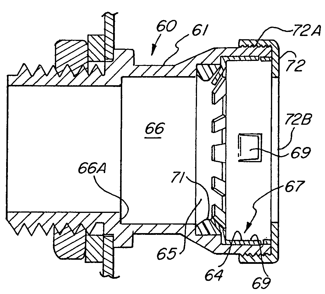
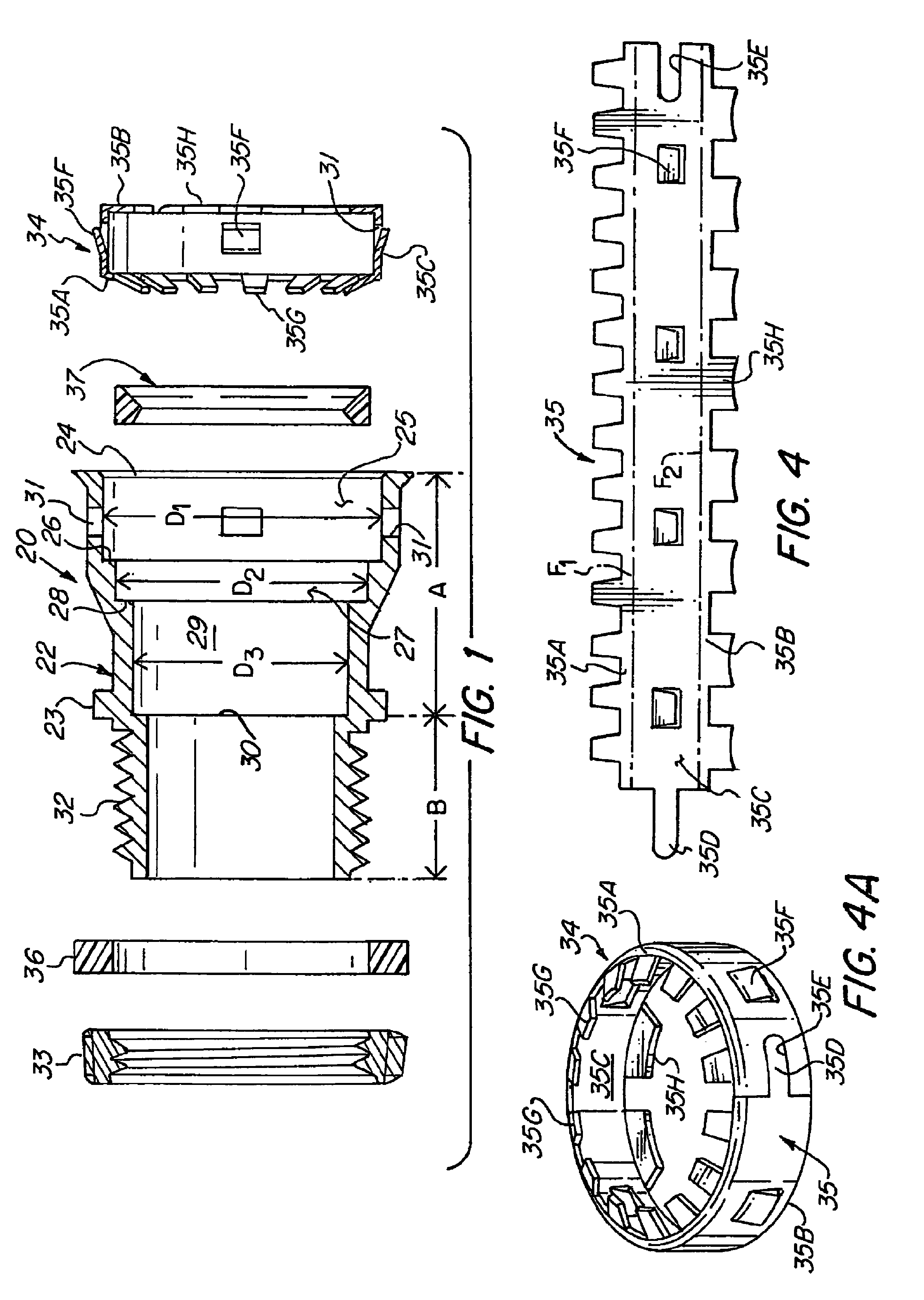
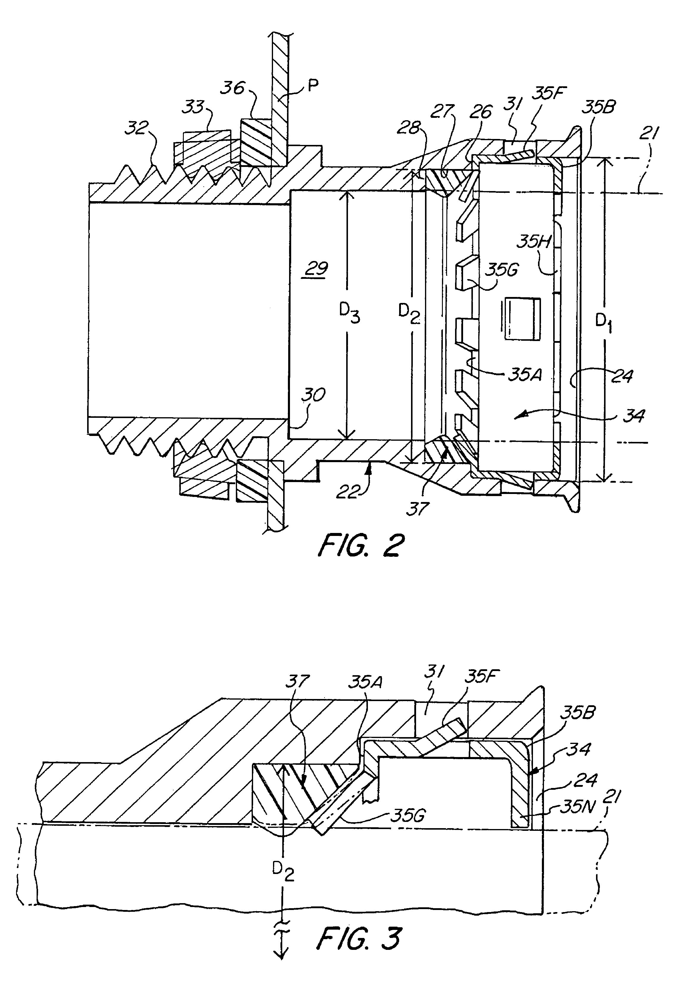
[0035]Referring to the drawings, FIGS. 1 to 4 illustrate an electrical connector or fitting 20 for attaching a conduit or an electric metal tube (EMT) 21 to an electric box or panel (not shown). Tube or conduit as interchangeably used herein are to be accorded their usual dictionary definition unless otherwise specified. The connector or fitting 20 includes a connector body 22 having an inlet portion A and an outlet portion B. Circumscribing the connector body exteriorly thereof is a radially outwardly extending flange 23, which functions as a stop to limit the distance the connector 20 may be inserted through a knockout hole of an electric box or panel, P.

[0036]As best shown in FIG. 1, the inlet portion A of the connector body 22 is formed so as to define an enlarged inlet opening circumscribing and defining an outer chamber 25 having a diameter D1, terminating at the inner end thereof by a shoulder 26. Concentrically disposed adjacent the outer chamber 25 is an intermediate chambe...


PUM


Abstract

An electrical fitting in the form of a connector or coupler for connecting an electric metal tube to an electrical box or panel or to one another. The fitting includes a body having an inlet end portion, an outlet end portion and a bore extending therethrough. An unidirectional locking device is disposed in an outermost chamber and a sealing washer disposed in an intermediate chamber. A split ring having an angularly bent leading end is provided with a series of offset circumferentially spaced unidirectional gripping tangs. The locking device may also be provided with a series of tube support tangs at the trailing end. Also, the locking device includes a tang forming an electrical bonding or ground between tubes, locking device and connector body.

Description

FIELD OF THE INVENTION[0001]This invention relates generally to electrical connectors or fittings for use with electrical metal tubes (EMT), and more specifically to a “push-in” connector for attaching an electric metal tube to an electric box or panel or for connecting one electric metal tube to another electric metal tube.BACKGROUND OF THE INVENTION[0002]Various types of connectors or fittings for connecting tubes or conduits to a structure or to one another are known, as exemplified in U.S. Pat. Nos. 4,123,090; 5,284,582; 5,695,224; 6,334,634; 6,450,550; 6,464,266; 6,517,124; 6,663,145; 6,670,553; 6,765,143 and 6,913,292. Generally, the known connectors or fittings are relatively complex. Many consist of a relatively large number of component parts that require assembly which may not be cost effective and / or practical for their intended purpose. Further, some of the known connectors or fittings are not suitable for use with electrical metal conduits or tubes. Notwithstanding the ...

Claims


Application Information

Patent Timeline
Patent Type & Authority Patents(United States)
IPC IPC(8): F16L19/08
CPCF16L5/06F16L37/091H02G3/0666
Inventor AURAY, DELBERTSMITH, LAWRENCE J.
Owner BRIDGEPORT FITTINGS LLC
Why Eureka
Try Eureka