Slag reduction pump

a technology of slag reduction and pump, which is applied in the direction of machines/engines, liquid fuel engines, borehole/well accessories, etc., can solve the problems of prior art attempts to protect downhole components from solid particles that have not been effective or otherwise undesirable, and particles tend to accelerate the wear of downhole components

Active Publication Date: 2010-11-30
BAKER HUGHES ESP INC
View PDF14 Cites 40 Cited by
  • Summary
  • Abstract
  • Description
  • Claims
  • Application Information

AI Technical Summary

Problems solved by technology

Unfortunately, many oil wells produce fluids that contain large amounts of sold particles, or “slag,” that are detrimental to downhole pumping components.
These and other particles tend to accelerate wear on downhole components as the solid particles are carried through the downhole pumping system with the produced fluid.
Despite the recognition of these problems, prior art attempts to protect downhole components from solid particles have proven ineffective or otherwise undesirable.

Method used


Image

  • Slag reduction pump
  • Slag reduction pump
  • Slag reduction pump

Examples


Embodiment Construction

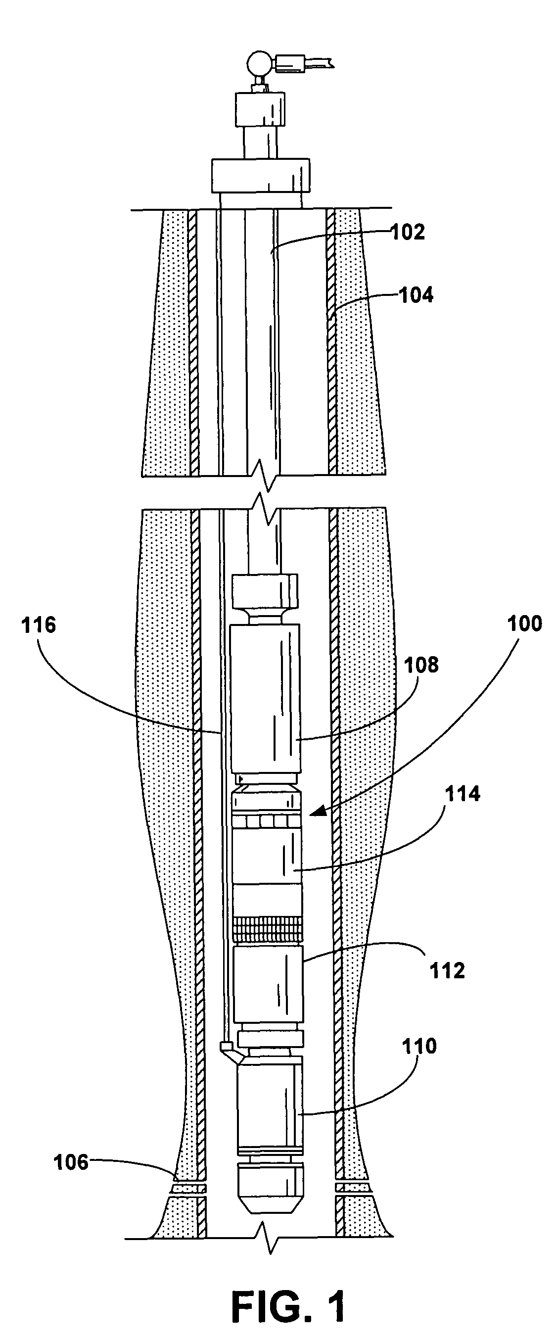
[0012]In accordance with a preferred embodiment of the present invention, FIG. 1 shows an elevational, diagrammatic view of a pumping system 100 attached to production tubing 102. The pumping system 100 and production tubing 102 are disposed in a wellbore 104, which is drilled for the production of a fluid such as water or hydrocarbons. The production tubing 102 connects the pumping system 100 to a wellhead located on the surface. Although the pumping system 100 is primarily designed to pump hydrocarbon products, it will be understood that the present invention can also be used to move other fluids. The wellbore 104 preferably includes at least one set of perforations 106 through the wellbore 104 to permit the introduction of fluid from the producing geologic formations into the wellbore 104. The pumping system 100 is well-suited for deployment above the perforations 106 or in a “sumped” configuration below the perforations 106. Additionally, or in the alternative, the pumping syste...


PUM


Abstract

A grinder pump assembly includes at least one grinder pump stage that has a diffuser and an impeller. The grinder pump assembly also includes a diffuser cap that includes cap contact surfaces. The impeller includes a plurality of upper vanes and lower vanes. The diffuser includes a plurality of lower contact surfaces, a plurality of diffuser vanes and plurality of upper contact surfaces. The upper vanes of the impeller are configured to rotate in proximity with the lower contact surfaces on the diffuser. The lower vanes of the impeller are configured to rotate in proximity with the cap contact surfaces. Multiple grinder pump stages may be used within a single grinder pump assembly.

Description

RELATED APPLICATIONS[0001]This application claims the benefit of U.S. Provisional Patent Application Ser. No. 60 / 796,629, entitled “Grinder Pump for Oil Well Fluids,” filed May 2, 2006, the disclosure of which is herein incorporated.FIELD OF THE INVENTION[0002]This invention relates generally to the field of downhole pumping systems, and more particularly to a downhole pumping system well suited for pumping fluids with entrained solid particles.BACKGROUND[0003]Submersible pumping systems are often deployed into wells to recover hydrocarbons from subterranean reservoirs. Typically, a submersible pumping system includes a number of components, including an electric motor coupled to one or more pump assemblies. Production tubing is connected to the pump assemblies to deliver the hydrocarbons from the subterranean reservoir to a storage facility on the surface. Each of the components in a submersible pumping system must be engineered to withstand the inhospitable downhole environment.[0...

Claims


Application Information

Patent Timeline
Patent Type & Authority Patents(United States)
IPC IPC(8): F04D29/44
CPCE21B43/128F04D7/045F04D29/2288F04D13/10Y10S415/901
Inventor PHILLIPS, HAROLD LEON
Owner BAKER HUGHES ESP INC
Why Eureka
Try Eureka