Methods and apparatus to facilitate sealing high pressure joints

a technology of bolted joints and sealing methods, which is applied in the direction of fluid pressure sealed joints, mechanical equipment, sleeve/socket joints, etc., can solve the problems of affecting the performance of either turbine engine, and machining the flanges to the finish required to prevent leakage may be a difficult and time-consuming task, so as to and facilitate reducing fluid leakag

Inactive Publication Date: 2010-12-07
GENERAL ELECTRIC CO
View PDF21 Cites 8 Cited by
  • Summary
  • Abstract
  • Description
  • Claims
  • Application Information

AI Technical Summary

Benefits of technology

[0004]In one aspect, a method for positioning a pressure vessel first mating surface adjacent to a second mating surface is provided. The method comprises inserting a seal assembly into a groove defined in the first mating surfaces such that a portion of the seal assembly extends outwardly from the first mating surface, positioning the second mating surface in close proximity to the first mating surface such that the portion of the seal assembly extending outwardly from the first mating surface is received within a groove defined in the second mating surface, and positioning the first mating surface adjacent to the second mating surface such that the seal assembly facilitates reducing fluid leakage between the first and second mating surfaces by creating a tortuous path against leakage.
[0005]In another aspect, a coupling system for use in pressure vessels is provided. The coupling system includes a first component, a second component, and a sealing assembly. The first component includes a mating surface and a groove defined within the mating surface. The second component includes a mating surface and a groove defined within the mating surface. The second component is positioned adjacent to the first component such that the first and second mating surfaces are substantially flush against each other. The sealing assembly is positioned at least partially within the first component mating surface groove and the second component mating surface groove and extends between the first and second components to facilitate reducing fluid leakage therebetween.
[0006]In a further aspect, a pressure vessel is provided. The pressure vessel includes a first mating surface, a second mating surface, and a sealing assembly. The first mating surface includes a groove defined therein. The second mating surface includes a groove defined therein. The second mating surface is positioned substantially flush against the first mating surface. The sealing assembly is positioned within the first and second mating surface grooves to facilitate reducing fluid leakage between the first and second mating surfaces.

Problems solved by technology

Within known power generation systems, leakage from a high pressure region through a bolted joint to a region of lower pressure may adversely affect the performance of the system.
Leakage of the steam and gas from the respective turbine engine to areas of lower pressure may be detrimental to the performance of either turbine engine.
However, because of the size and complexity of the components being coupled together, machining the flanges to the finish required to prevent leakage may be a difficult and time-consuming task.
Moreover, depending on the application, fluids within areas of high pressure may still leak through such connections.

Method used


Image

  • Methods and apparatus to facilitate sealing high pressure joints
  • Methods and apparatus to facilitate sealing high pressure joints
  • Methods and apparatus to facilitate sealing high pressure joints

Examples


Embodiment Construction

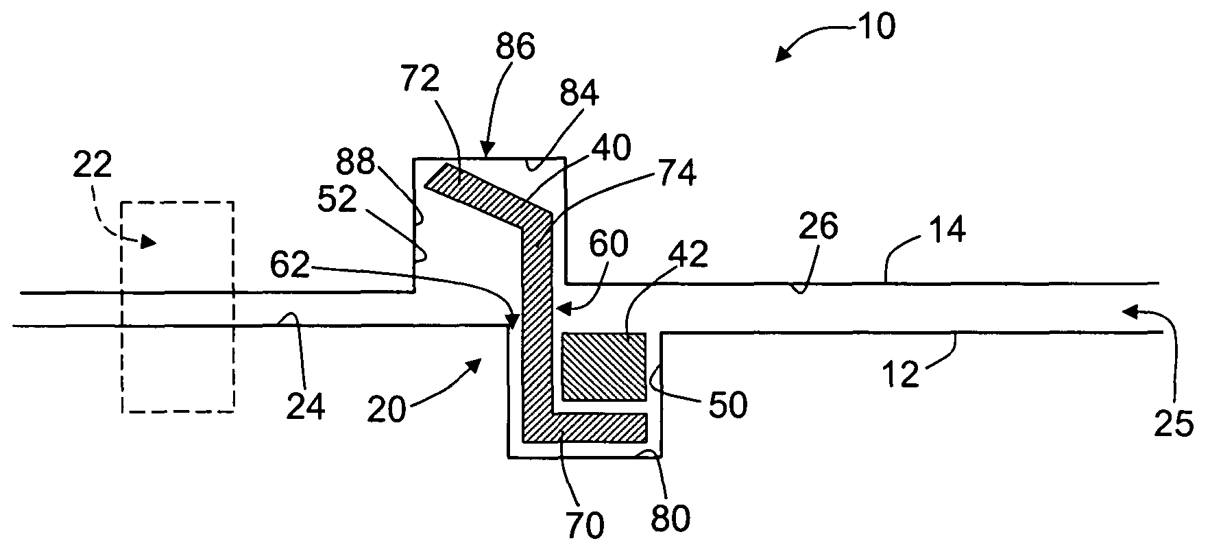
[0010]As used herein, the term “pressure vessel” may include any vessel, container, component, or portion thereof, that is designed to contain a pressurized fluid that is at a pressure above that of atmospheric pressure. For example, pressure vessels may include, but are not limited to, turbine casings, turbine shells, steam separators, vavle casings, pipe joints, and / or pipe flanges. The aforementioned examples are intended as exemplary only, and thus are not intended to limit in any way the definition and / or meaning of the terms “pressure vessel”. In addition, as used herein the term “component” may include any object that has been, or may be, manufactured.

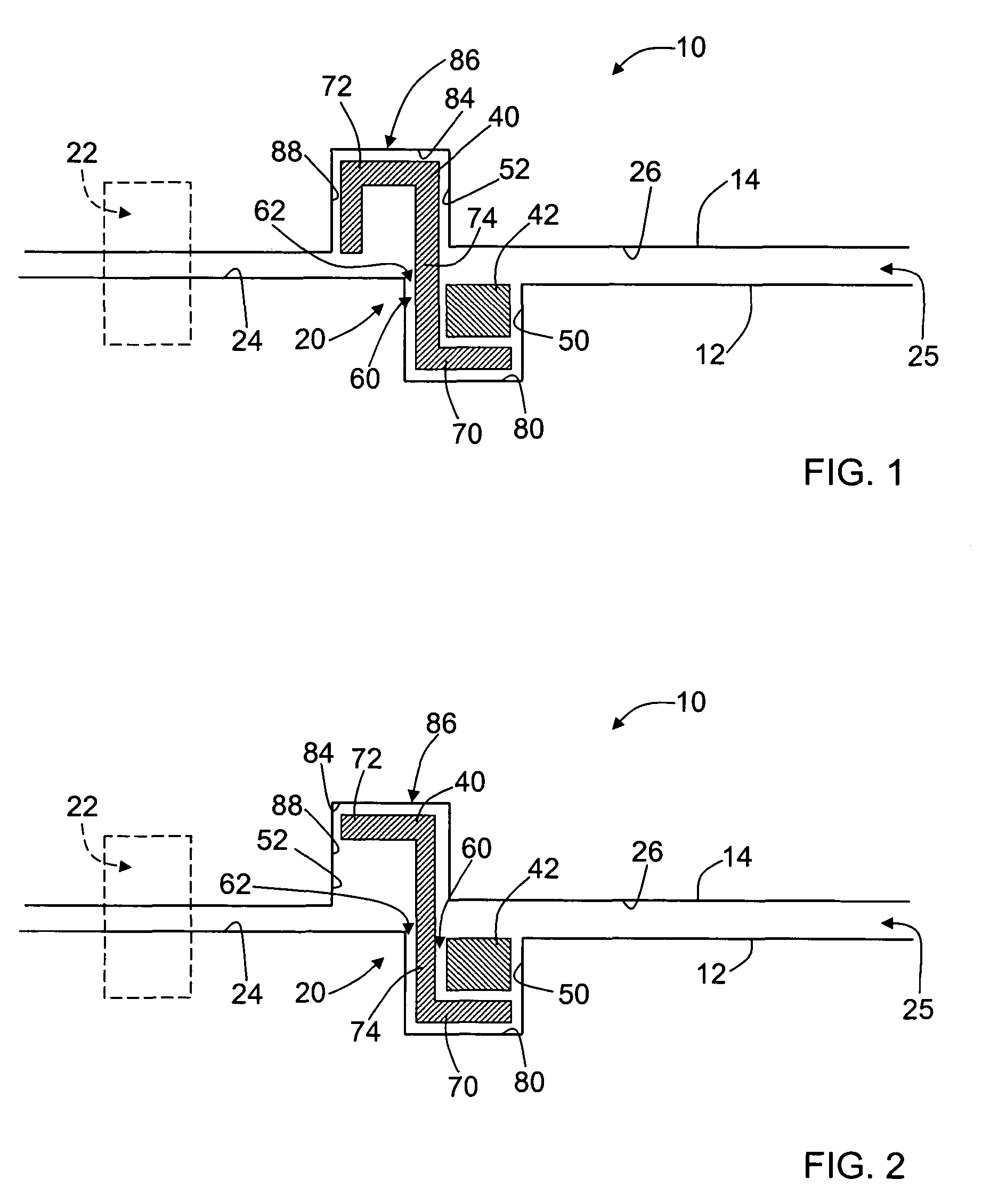
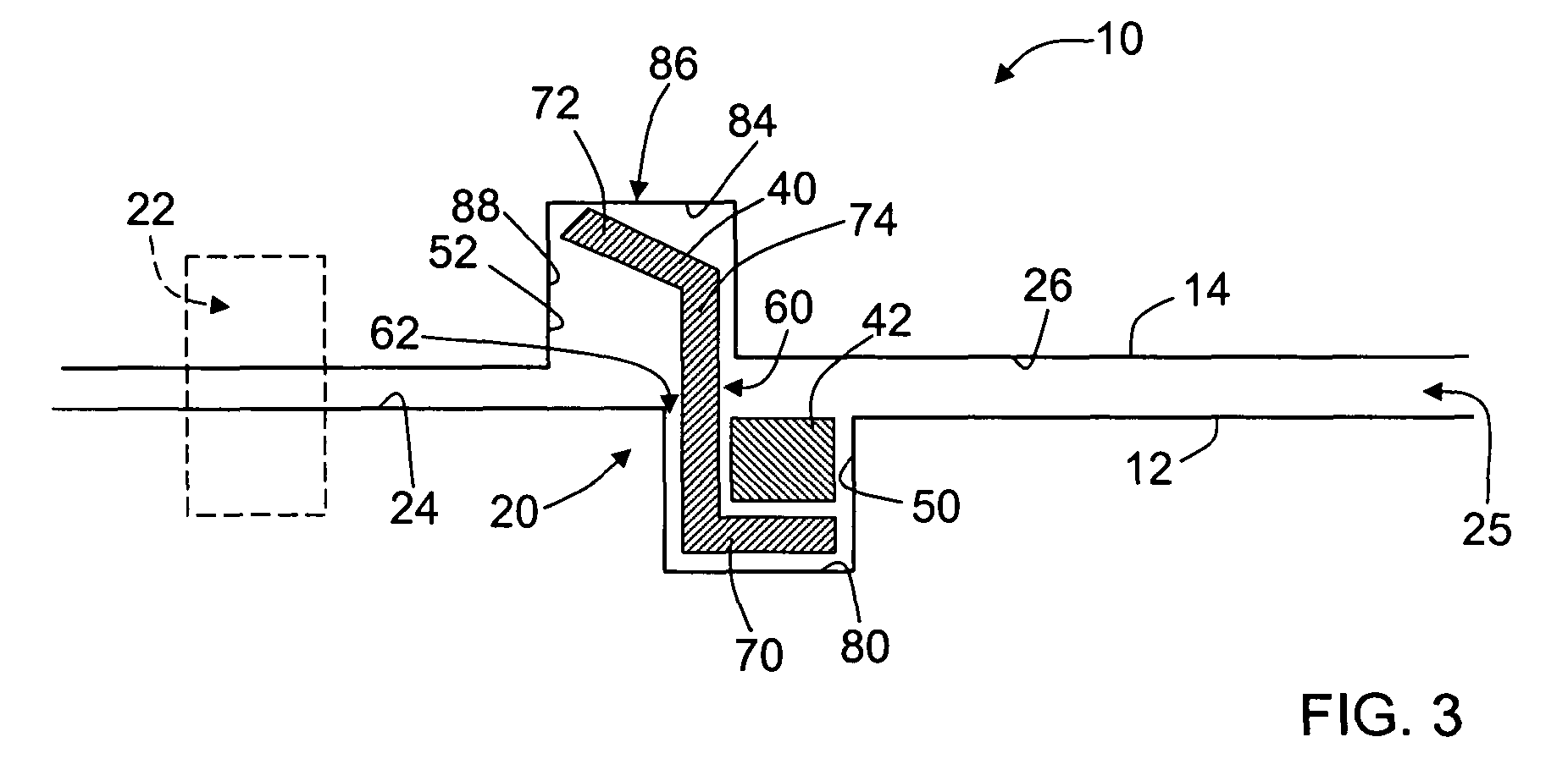
[0011]FIG. 1 is schematic illustration of an exemplary coupling system 10 for use with pressure vessels and pressurized fluids. FIG. 2 is an alternative embodiment of coupling system 10. FIG. 3 is an further alternative embodiment of coupling system 10. In each embodiment, and as described in more detail below, coupling system 1...


PUM


Abstract

A method and apparatus facilitates coupling a pressure vessel first mating surface to a second mating surface. The method comprises inserting a seal assembly into a groove defined in the first mating surfaces such that a portion of the seal assembly extends outwardly from the first mating surface, positioning the second mating surface in close proximity to the first mating surface such that the portion of the seal assembly extending outwardly from the first mating surface is received within a groove defined in the second mating surface, and such that the seal assembly facilitates reducing fluid leakage between the first and second mating surfaces.

Description

BACKGROUND OF THE INVENTION[0001]This application relates generally to bolted joints and, more particularly, to methods and apparatus for coupling high pressure bolted joints.[0002]Within known power generation systems, leakage from a high pressure region through a bolted joint to a region of lower pressure may adversely affect the performance of the system. For example, the steam flow path in a steam turbine engine and the gas flow path in a gas flow turbine engine may be at a much higher pressure than a pressure of the surrounding ambient flow. Leakage of the steam and gas from the respective turbine engine to areas of lower pressure may be detrimental to the performance of either turbine engine.[0003]To facilitate reducing leakage from high pressure regions to regions of lower pressure, flanges used with bolted connections are machined until the mating face of each flange is substantially smooth and flat. Moreover, each bolt used with such connections is then torqued such that th...

Claims


Application Information

Patent Timeline
Patent Type & Authority Patents(United States)
IPC IPC(8): F16J15/02
CPCF16L17/06F16L23/16
Inventor KOWALCZYK, MARK W.
Owner GENERAL ELECTRIC CO
Why Eureka
Try Eureka